-8-
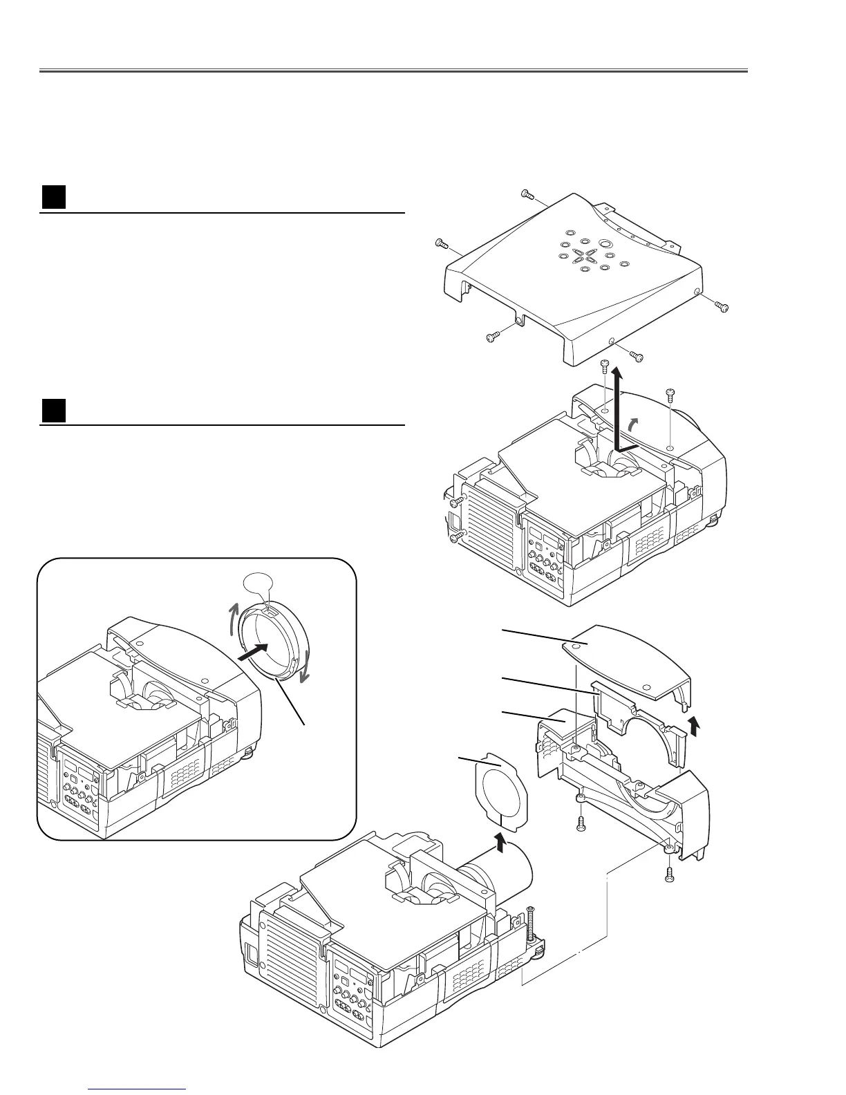
1 Remove 5 screws A, 2 screws B, and loosen 2 screws
C, and then take the Cabinet Top upward off.
Note: If you want to remove the Cabinet Front-Top only,
you do not need to remove screws A.Remove 2 screws B
and Lens Front Cover.
■ Mechanical Disassemblies
Mechanical disassemble should be made following procedures in numerical order.
Following steps show the basic procedures, therefore unnecessary step may be ignored.
Caution:
The parts and screws should be placed exactly the same position as the original otherwise it may cause loss of
performance and product safety.
Fig.1
1 Tu rn the Lens Front Cover counter-clockwise and to take
it off by pulling forward as shown in Fig.2-1.
2 Remove the Cabinet Front-Top, Lens Cover Holder and
Lens Cover upward off.
3 Remove 2 screws D to take the Cabinet Front off.
4 Remove the RC Board and speakers on the Cabinet
Front.
Fig.2
-2
Cabinet Top removal
1
Cabinet Front removal
2
 Loading...