34 SARTORIUS MC 5 Balance Stand 1/94
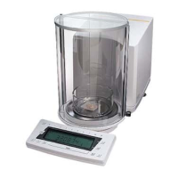
MC 5
Description of the Microbalance:
The MC5 consists of two major units:
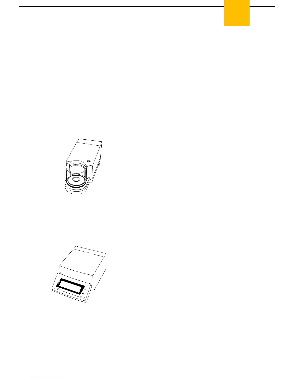
a. Weighing Cell
Located inside the weighing cell are the mechanical coil/beam
system, the servomotor subassembly for internal weight
application, the draft shield drive and bearing system, including the
following:
System connector PCB
(See page 8 Exploded-view diagram 3.....No.318)
System PCB
(see page 8 Exploded-view diagram 3.....No.304)
Weight servomotor PCB
(see page 8 Exploded-view diagram 3.....No.311)
Null indicator PCB
(see page 10 Exploded-view diagram 4.....No.406)
Draft shield PCB
(see page 12 Exploded-view diagram 5.....No.504)
b. Display Unit
The display unit houses the following components:
Main PCB
(see page 4 Exploded-view diagram 1.....No.104)
Analog PCB
(see page 4 Exploded-view diagram 1.....No.107)
Data output PCB
(see page 4 Exploded-view diagram 1.....No.105)
The LCD of the display unit is attached to the following:
Display PCB module
(see page 4 Exploded-view diagram 1.....No.111)