Fi
.1
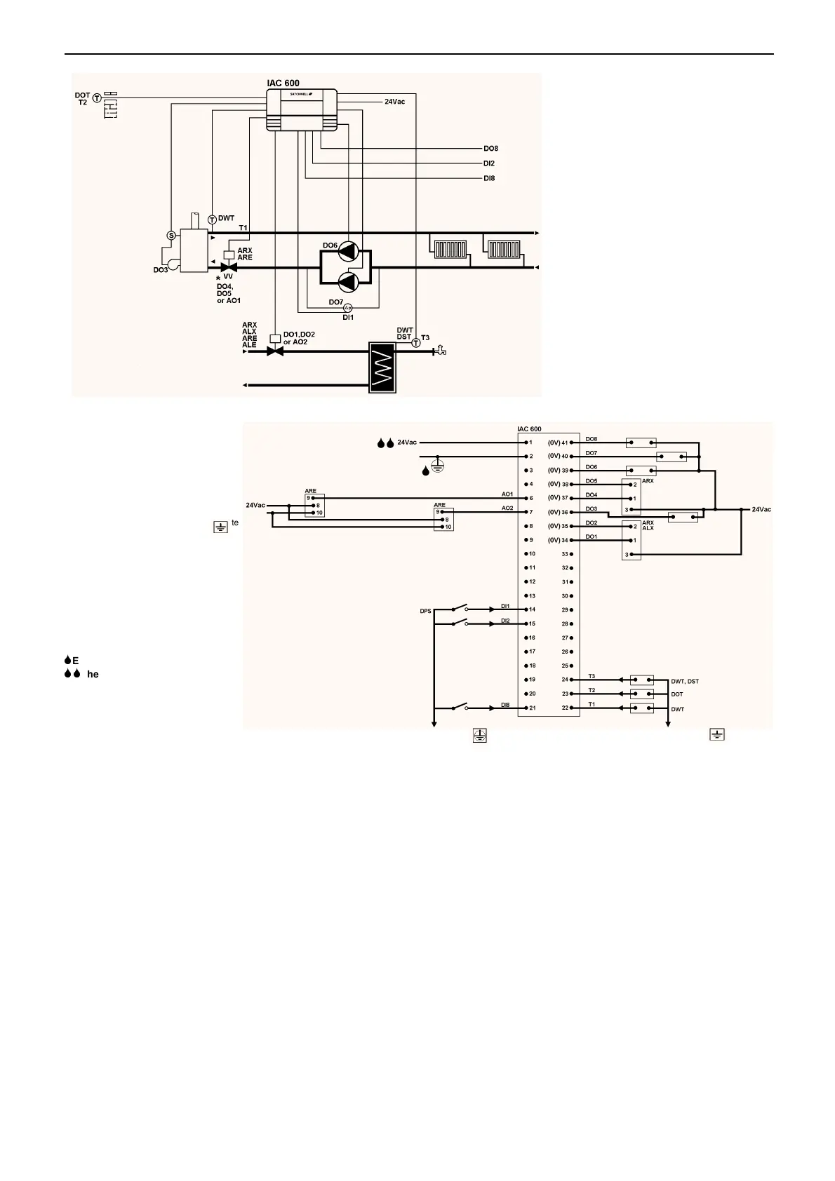
PRESET 1 – Boiler Compensation and separate HWS System
Pumps failed signal
Time re-synchronization
Clear pumps failed
Pump 1
Pump 2
Backend
Valve
High Limit
Thermostat
(hand reset) and
burner controls.
Use of the backend valve is
optional. If the backend valve is
used it should be mechanically or
electrically restricted to stop it
fully closing.
*
Flow
Pumps Failed
Pump 2
Pump 1
Boiler
HWS
Valve
HWS
Valve
Supply
Backend Valve
HWS Sensor
Outside Sensor
Flow Sensor
Backend
Valve
Pump
Clear Pumps Failed
Time
re-synchronization
Connect to any IAC
isolated ground
terminal
Connect to any IAC 600
terminal
Note:–
The actual terminal block is a
double block running across the
bottom of the IAC. The top (double
height) block contains terminals 1
to 33 and the bottom (single height)
contains 34 to 41 and all of the
Ground and isolated Ground
terminals. Terminal numbers run
from left to right.
6
Ensure Terminal 2 is earthed.
66
The 24Vac Supply must be
fused with a 2A fuse.
Terminal 5 is not used.
If an earth busbar is to be used
then it must be connected to a
single Ground terminal on the IAC
by a single cable which should be
as short as possible and no more
than 150mm long. Earth wire
minimum 30/0.25 (1.5mm
2
)
Stranded Cable.
Any IAC 600
terminal
TIME SCHEDULES
08:00 to 17:00
Connected to the compensator and HWS loops.
The time re-s
nchronization input will re-s
nchronize the IAC time to
midni
ht Monda
.
COMPENSATOR
Schedule OUTSIDE SUPPLY
080
10 50
20 20
The outside temperature value is fed into a look-up table. The result
is passed to the controller RPW input and is used to set the controller
set value.
Proportional Band 10
Inte
ral Action 300
Derivative Action 0
Ramp Time 60
Sample Time 10
HWS
The HWS valve will open at 38
°
C and close at 40
°
C. Note this is an
on/off action and is not modulatin
.
BOILER/BACKEND VALVE
The boiler and backend valve are both enabled when the control
demand si
nal exceeds 10% and disabled when it drops below 5%.
The boiler output has a hold off time of 15 Seconds and the backend
valve output has hold off time of 5 Seconds.
The backend valve should be mechanicall
or electricall
limited so
that it remains open at a minimum of 10% to enable heat dissipation
from within the boiler.
PUMPS
Two pump outputs are supplied, Pump 1 normall
runs when the
controller is re
uestin
heat. In the event of pump 1 failin
to run, a
differential pressure switch si
nals the IAC which enables pump 2.
In the event of pump 2 failin
the "pumps failed" output is enabled. A
"clear pumps failed" input is supplied to enable the failed pumps to
be used once the
have been repaired or reset.
VALVE OPTIONS
Both the HWS and backend valve actuators ma
be 0 to 10Vdc or
24Vac driven, it should be noted however that valve operation in all
cases is purel
on/off and not modulatin
.
05/98 15 - 24 DS 2.951A



 To Next Page