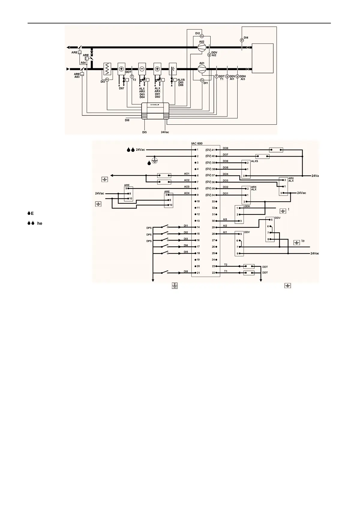
Fi
.4
Note:–
The actual terminal block is
a double block running
across the bottom of the
IAC. The top (double
height) block contains
terminals 1 to 33 and the
bottom (single height)
contains 34 to 41 and all of
the Ground and isolated
Ground terminals.
Terminal numbers run
from left to right.
6
Ensure Terminal 2 is
earthed.
66
The 24Vac Supply must
be fused with a 2A fuse.
Terminal 5 is not used.
If an earth busbar is to be
used then it must be
connected to a single
Ground terminal on the IAC
by a single cable which
should be as short as
possible and no more than
150mm long. Earth wire
minimum 30/0.25 (1.5mm
2
)
Stranded Cable.
PRESET 4 – Full air-conditioning including variable Fan Speed Control
Exhaust
Air
Outside
Air
Time re-synchronization
Fan Fail Clear
Single Step Humidifier
Pre-heater
Common Cooler
Battery
Supply
Humidity
Heater
Battery
Extract/
Recirc.
Damper
Supply
Supply Fan
Speed
Supply
Velocity
Sensor
Extract Velocity
Sensor
Pre-heater Temperature Sensor
Supply
Extract
Connect to any IAC 600
isolated ground
terminal
Connect to any IAC 600
terminal
Connect to any
IAC 600
terminal
Supply
Damper
Supply Temperature Sensor
Filter Dirty
Humidifier
Extract Fan
Speed
Connect to any IAC 600
terminal
Connect to any
IAC 600
terminal
Connect to any IAC 600
terminal
Smoke
Fan Fail Clear
Time re-synchronization
TIME SCHEDULES
08:00 to 17:00
Connected to the temperature and humidit
loops.
The time re-s
nchronization input will re-s
nchronize the IAC time to
midni
ht Monda
.
TEMPERATURE LOOP
Set value 50
°
C
Sta
e 1 and 2
Proportional Band 10
Inte
ral Action 300
Derivative Action 0
Ramp Time 60
Sample Time 10
The suppl
and extract fans are speed controlled from the velocit
sensors, their set values bein
determined b
the heatin
and
coolin
control demand si
nals.
The main temperature loop operates a heater batter
and common
cooler batter
. The dampers are modulated from the heatin
and
coolin
control demand si
nals and have a minimum fresh air settin
of 30%. In the event of the smoke switch activatin
the
recirculation/extract dampers will
o to 100%, the suppl
damper to
0%, the suppl
fan will
o to 0% and the extract fan to 75% of the full
fan speed.
The temperature loop is overridden off if the fans stop.
HUMIDITY LOOP
Set value 19% RH
Sta
e 1 and 2
Proportional Band 10
Inte
ral Action 300
Derivative Action 0
Ramp Time 60
Sample Time 10
The humidit
loop operates a humidifier and common cooler batter
.
The humidifier can be a sin
le switched output operatin
at 0% of the
control si
nal or a modulatin
valve and actuator.
The humidit
loop is overridden off if the fans stop.
PREHEATER LOOP
The preheater output is a simple on/off tri
ered at a set temperature.
On at 1
°
C
Off at 1
°
C
SMOKE OVERRIDE
Under smoke conditions the followin
actions will betaken:
Suppl
Damper 0%
Recirculation/Extract Damper 100%
Suppl
Fan Off
Extract Fan 75%
FAN SPEED LOOPS
Sta
e 1 and 2
Proportional Band 10
Inte
ral Action 300
Derivative Action 0
Ramp Time 60
Sample Time 10
Look-up Table IN OUT
00
10 2
20 3
30 4
40 6
50 10
60 16
70 25
80 40
90 63
100 100
There are two fan speed control loops, one for the suppl
and one for
the extract fan. The set values for the fan speed loops are derived
from the temperature loop heatin
and coolin
control si
nals.
If the fan fails the temperature and humidit
controllers are
overridden off. A di
ital input is supplied to clear the fan failure and
remove the controller override.
DS 2.951A 18 - 24 05/98



 To Next Page