Chapter 2 Installation Electrical Installation
EM13x Series SMART MULTIFUNCTION METER 25
2.4 Electrical Installation
The equipment installation shall conform to the following
instructions:
a) a switch or circuit-breaker shall be included in the building
installation as close as possible to the equipment supply
voltage;
b) It shall be in close proximity to the equipment and within
easy reach of the OPERATOR;
c) It shall be marked as the disconnecting device for the
equipment.
d) Before installing, ensure that all incoming power sources are
shut OFF. Failure to observe this practice can result in serious
or even fatal injury and damage to equipment.
e) The current sensors may not be installed in a panel where
they exceed 75% of the wiring space of any cross-sectional
area within the panel.
Connecting the wires
All conductors must be stranded copper. All conductors and insulation
systems and crimped devices must be appropriate for the application.
SATEC requires using crimped ferrules on stranded wire.
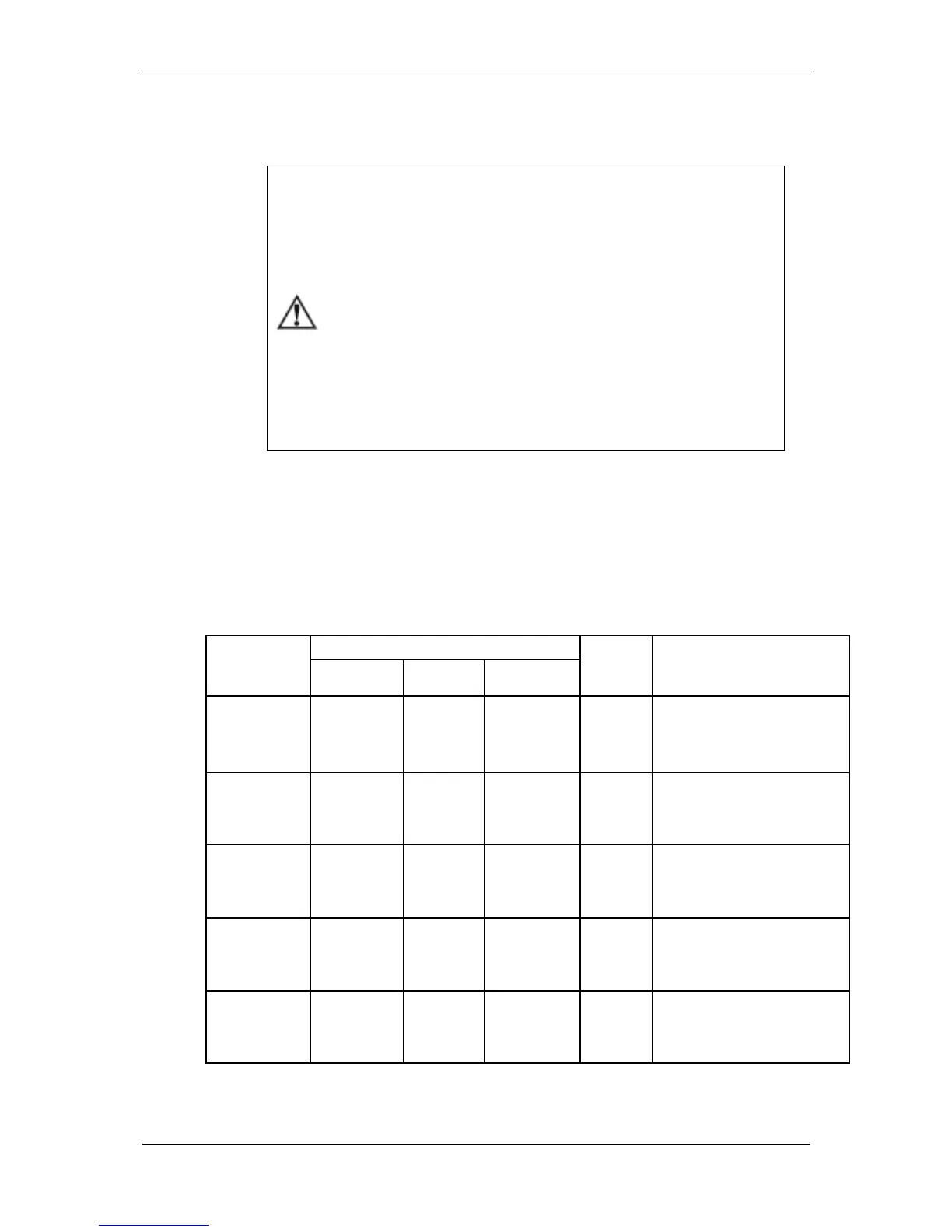
Table 3 below summarizes the different conductors’ sizes to be used in
the EM133 external connections.
Table 2: Wiring Configurations
Aux. Power
Supply Inputs
L/+, N/-
Use 600V insulated conductors
Required crimped ferrule:
Panduit (22AWG) F75-10-M
Panduit (12AWG) F81-15-M
Voltages Inputs
V1, V2, V3, Vn
Use 600V insulated conductors
Required crimped ferrule:
Panduit (22AWG) F75-10-M
Panduit (12AWG) F81-15-M
Current Inputs
I1, I2, I3, N
Use 600V insulated conductors
Required crimped ferrule:
Panduit (22AWG) F75-10-M
Panduit (10AWG) F82-15-M
Current Inputs
I1, I2, I3, N
Use 600V insulated conductors
Required crimped ferrule:
Panduit (6AWG) F84-15-M
Panduit (4AWG) F85-15-M
Use 600V insulated conductors
Required crimped ferrule:
Panduit (22AWG) F75-10-M
Panduit (12AWG) F81-15-M

 Loading...