Chapter 2 Installation Electrical Installation
32 EM13x Series SMART MULTIFUNCTION METER
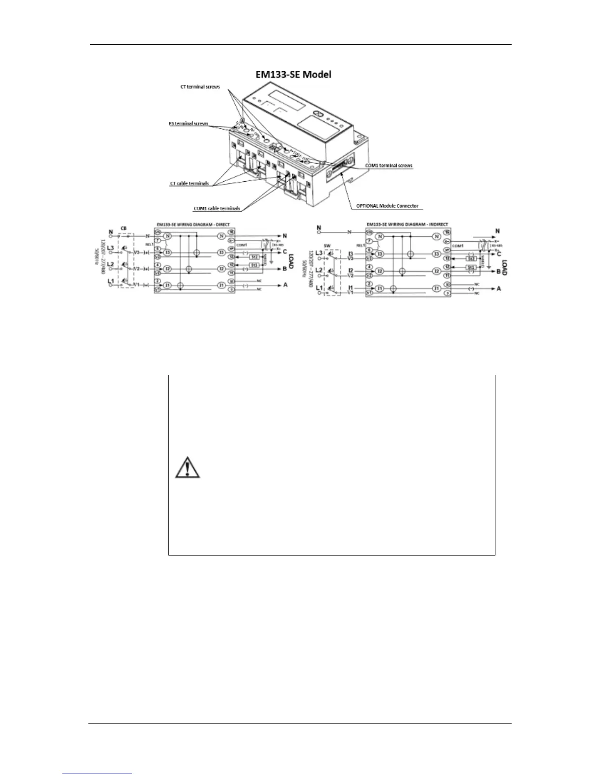
Figure 2-7b Terminals View EM133-SE Model
Power Source Connection
The equipment installation shall conform to the following
instructions:
a) a switch or circuit-breaker shall be included in the building
installation as close as possible to the equipment supply
voltage;
b) It shall be in close proximity to the equipment and within
easy reach of the OPERATOR;
c) It shall be marked as the disconnecting device for the
equipment.
d) Before installing, ensure that all incoming power sources are
shut OFF. Failure to observe this practice can result in serious
or even fatal injury and damage to equipment.
e) The current sensors may not be installed in a panel where
they exceed 75% of the wiring space of any cross-sectional
area within the panel.
The power source can be a dedicated fuse or a monitored voltage if it is
within the instrument power supply range.
To connect an AC Auxiliary Power Supply (EM133 model only):
Connect the Line wire to terminal (9).
Connect the Neutral wire to terminal (10)
To connect to a DC Auxiliary Power Supply (EM133 and EM133-21DC models only):
Connect the positive wire to terminal (9)
Connect the negative wire to terminal (10)

 Loading...