SATEL OPAL 3
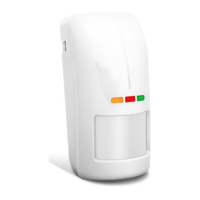
LED indicators
The LEDs indicate:
warm-up – all LEDs flashing alternately for about 40 seconds;
motion detected by microwave sensor – green LED ON for 4 seconds;
motion detected by PIR sensor – yellow LED ON for 4 seconds;
alarm – red LED ON for 2 seconds;
trouble – all LEDs ON for entire duration of the trouble.
The LEDs are also used in the configuration mode (see: “Configuring the detector”).
You can enable / disable the LEDs. When disabled, the LEDs will not indicate the states
described above.
Enabling the LEDs by using a jumper
If you put a jumper across the LED pins, the LEDs will be enabled, i.e. they will indicate the
events described above (the LED indicators can’t be enabled / disabled remotely). If you do
not put a jumper across the pins, the LEDs will be disabled, but they can be
enabled / disabled remotely.
Remote LEDs enable / disable
The LED terminal is provided to allow remote LEDs enable / disable. When the terminal is
connected to common ground, the LEDs are enabled. When the terminal is disconnected
from common ground, the LEDs are disabled.
If the detector is used in the INTEGRA / INTEGRA Plus alarm system, you can connect to
the terminal the OC type control panel output programmed e.g. as “Zone test status”
or “BI switch”.
Remote configuration mode enable / disable
The SVCE terminal is provided to allow remote configuration mode enable / disable.
The configuration mode is enabled, when the terminal is connected to the common ground.
If the detector is used in the INTEGRA / INTEGRA Plus alarm system, you can connect to
the terminal the OC type control panel output programmed e.g. as “Service mode status”
or “BI switch”.
3. Electronics module
Do not remove the plastic cover from the circuit board to prevent damage to the
components located on the board.
Do not touch the pyroelectric sensor, so as not to soil it.