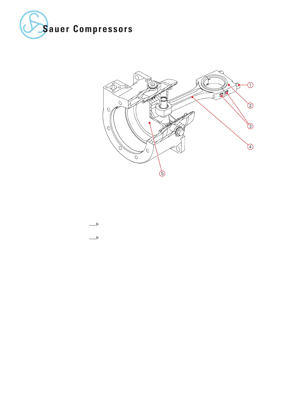
Fig. 11: Pistons and connecting rods (example with compression stage 1)
1 Connecting rod bolts
2 Lower part of the connecting rod
3 Numerical markings
4 Upper part of the connecting rod
5 Piston
1. Unscrew the connecting rod bolts through the opposite opening in the
crankcase.
2. Remove the upper section of the connecting rod together with the
piston from the crankcase. Leave the lower half of the connecting rod
on the crankshaft as a spacer block.
36 | WP5000 Basic WA 41013675 en GB 20190916