Section 4 – Camera Hardware
Page 43
4. Camera Hardware
This section describes the modular components that make up the CCD Camera System and how
they fit into the observatory, with all their connections to power and other equipment.
4.1. System Components
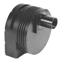
The ST-7XE, ST-8XE, ST-9XE, ST-10XE, ST-10XME and ST-2000XM CCD cameras consist of four
major components: the CCD Sensors and Preamplifier, the Readout/Clocking Electronics, the
Microcontroller, and the power supply. All the electronics are packaged in the optical head in
these cameras with an external desktop power supply.
The CCDs, Preamplifier, and Readout Electronics are mounted in the front of the optical
head. The optical head interfaces to the telescope through a 1.25 inch (or larger) draw tube,
sliding into the telescope's focus mechanism. The placement of the preamplifier and readout
electronics close to the CCD is necessary to achieve good noise performance. The
Microcontroller is housed in the rear of the Optical Head along with the interface logic to the PC
and Telescope.
4.2. Connecting the Power
The desktop power supply is designed to run off voltages found in most countries (90 to 240
VAC). In the field however, battery operation may be the most logical choice. In that case you
need to use the optional 12V power supply or a 12VDC to 110 VAC power inverter.
4.3. Connecting to the Computer
The ST-7XE, ST-8XE, ST-9XE, ST-10XE, ST-10XME and ST-2000XM CCD Cameras are supplied
with a 15 foot cable to connect the system to the host computer. The connection is between the
camera and the Host Computer's USB port. If it is necessary or desirable to extend the distance
between the camera and the computer, third party USB extenders such as the “Ranger” made
by Icron (http://www.icron.com
) may be used for remote operation up to 500 meters.
4.4. Connecting the Relay Port to the Telescope
The ST-7XE, ST-8XE, ST-9XE, ST-10XE, ST-10XME and ST-2000XM camera systems can be used
as autoguiders where the telescope's position is periodically corrected for minor variations in
the RA and DEC drives. The host software functions as an autoguider in three modes: the
Track mode, the SBIG patented Track and Accumulate mode, and the SBIG patented Self
Guided mode (except for the ST-1001E).
In the Track mode and Self Guided mode the host software corrects the telescope as
often as once every second to compensate for drift in the mount and drive system. The host
software and the CCD camera operate in tandem to repeatedly take exposures of the designated
guide star, calculate its position to a tenth of a pixel accuracy, and then automatically activate
the telescope's controller to move the star right back to its intended position. It does this
tirelessly to guide long duration astrophotographs.
In the Track and Accumulate mode the software takes a series of images and
automatically co-registers and co-adds the images to remove the effects of telescope drift.