Appendix A - Connector Pinouts
Page 69
A. Appendix A - Connector and Cables
A.1. Connector Pinouts for the AO7/CFW8/SCOPE port:
Pin Number Function
1 Chassis Ground
2 CFW-8 Pulse/AO-7 Data Out
3 Plus X (Active Low Open Drain)
6
4 Plus Y (Active Low Open Drain)
5 Signal Ground
6 Minus X (Active Low Open Drain)
7 Minus Y (Active LowOpen Drain)
8 +12 Volts Out (100mA max shared with I2C AUX)
9 +5 Volts Out (300 mA max shared with I2C AUX)
Shell Chassis Ground
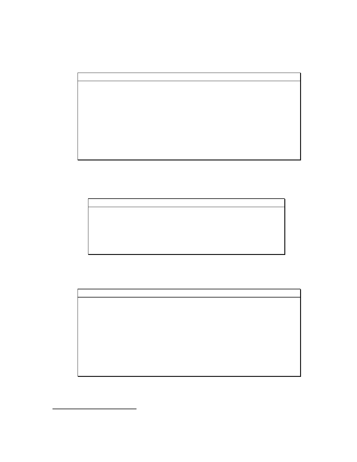
Table A1 Telescope Connector
A.2. Connector Pinouts for the power jack:
Pin Number Function
6, Shell Earth Ground
5 DC Ground
4 -12V DC, 100mA
3 No contact
2 +12V DC, 500mA
1 +5V DC, 2A
Table A2 Power Connector Power Jack
A.3. Connector Pinouts for the I2C AUX port:
Pin Number Function
1 +5V DC (300 mA max shared with AO7/CFW8)
2 No Contact
3 Serial Clock
4 Serial Data
5 Signal Ground
6 No Contact
7 No Contact
8 +12V DC (100mA max shared with AO7/CFW8)
9 +3.3V DC (500mA max)
Shell Chassis Ground
Table A3 I2C Accessory Port
6
The Open Drain outputs can sink 100 mA maximum