Programmable Logic P746/EN PL//G31
MiCOM P746 (PL) 7-
9
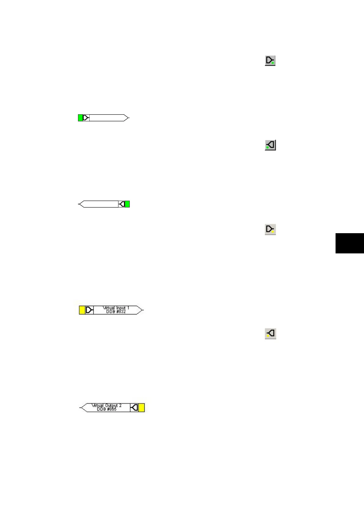
1.6.3 Input signal properties
Input Signal
Relay logic functions provide logic output signals that can be used for programming in PSL.
Depending on the relay functionality, operation of an active relay function will drive an
associated DDB signal in PSL.
For example DDB 1142 will be asserted in the PSL should the active terminal1 earth fault ,
stage 1 protection operate/trip.
DDB #1142
T1 IN>1 Trip
1.6.4 Output signal properties
Output Signal
Relay logic functions provide logic input signals that can be used for programming in PSL.
Depending on the relay functionality, activation of the output signal will drive an associated
DDB signal in PSL and cause an associated response to the relay function
For example, if DDB 651 is asserted in the PSL, it will block the terminal1 earth function
stage 1 timer.
DDB #651
T1 IN>1 TimeBlk
1.6.5 GOOSE input signal properties
GOOSE In
The Programmable Scheme Logic interfaces with the GOOSE Scheme Logic (see PSL
Editor online help or S1 Users manual for more details) by means of 32 Virtual inputs. The
Virtual Inputs can be used in much the same way as the Opto Input signals.
The logic that drives each of the Virtual Inputs is contained within the relay’s GOOSE
Scheme Logic file. It is possible to map any number of bit-pairs, from any subscribed device,
using logic gates onto a Virtual Input (see S1 Users manual for more details).
For example DDB 832 will be asserted in PSL should virtual input 1 operate.
PL
1.6.6 GOOSE output signal properties
GOOSE Out
The Programmable Scheme Logic interfaces with the GOOSE Scheme Logic by means of
32 Virtual outputs.
It is possible to map virtual outputs to bit-pairs for transmitting to any published devices (see
PSL Editor online help or S1 Users manual for more details).
For example if DDB 865 is asserted in PSL, Virtual Output 32 and its associated mappings
will operate.