Getting Started P746/EN GS/G31
MiCOM P746 (GS) 3-
9
1.5 Menu structure
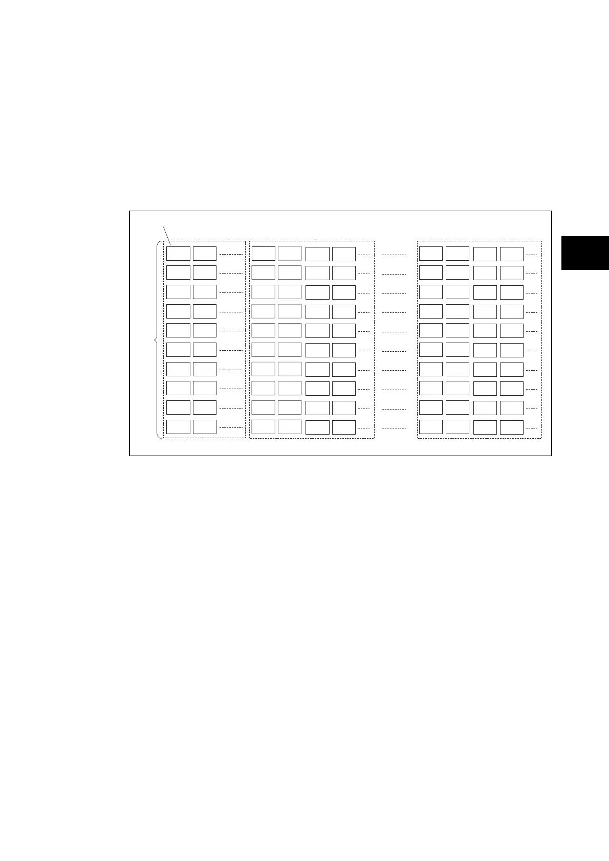
The relay’s menu is arranged in a tabular structure. Each setting in the menu is referred to
as a cell, and each cell in the menu may be accessed by reference to a row and column
address. The settings are arranged so that each column contains related settings, for
example all of the disturbance recorder settings are contained within the same column. As
shown in Figure 4, the top row of each column contains the heading that describes the
settings contained within that column. Movement between the columns of the menu can only
be made at the column heading level. A complete list of all of the menu settings is given in
the Menu Content Map at the end of this section.
Column
data
settings
Column header
Control & support
Group 1
Group 4
Up to 4 protection setting groups
System data
View records
DIFF
BUSBAR PROT
BUSBAR
OPTION
P0106ENb
INPUTS
LABELS
OUTPUT
LABELS
DIFF
BUSBAR PROT
BUSBAR
OPTION
INPUTS
LABELS
OUTPUT
LABELS
FIGURE 3: MENU STRUCTURE
All of the settings in the menu fall into one of three categories; protection settings,
disturbance recorder settings, or control and support (C&S) settings. One of two different
methods is used to change a setting depending on which category the setting falls into.
Control and support settings are stored and used by the relay immediately after they are
entered. For either protection settings or disturbance recorder settings, the relay stores the
new setting values in a temporary ‘scratchpad’. It activates all the new settings together, but
only after it has been confirmed that the new settings are to be adopted. This technique is
employed to provide extra security, and so that several setting changes that are made within
a group of protection settings will all take effect at the same time.
GS
1.5.1 Protection settings
The protection settings include the following items:
− Protection element settings
− Scheme logic settings
There are four groups of protection settings, with each group containing the same setting
cells. One group of protection settings is selected as the active group, and is used by the
protection elements.
1.5.2 Disturbance recorder settings
The disturbance recorder settings include the record duration and trigger position, selection
of analogue and digital signals to record, and the signal sources that trigger the recording.