Getting Started P746/EN GS/G31
MiCOM P746 (GS) 3-
7
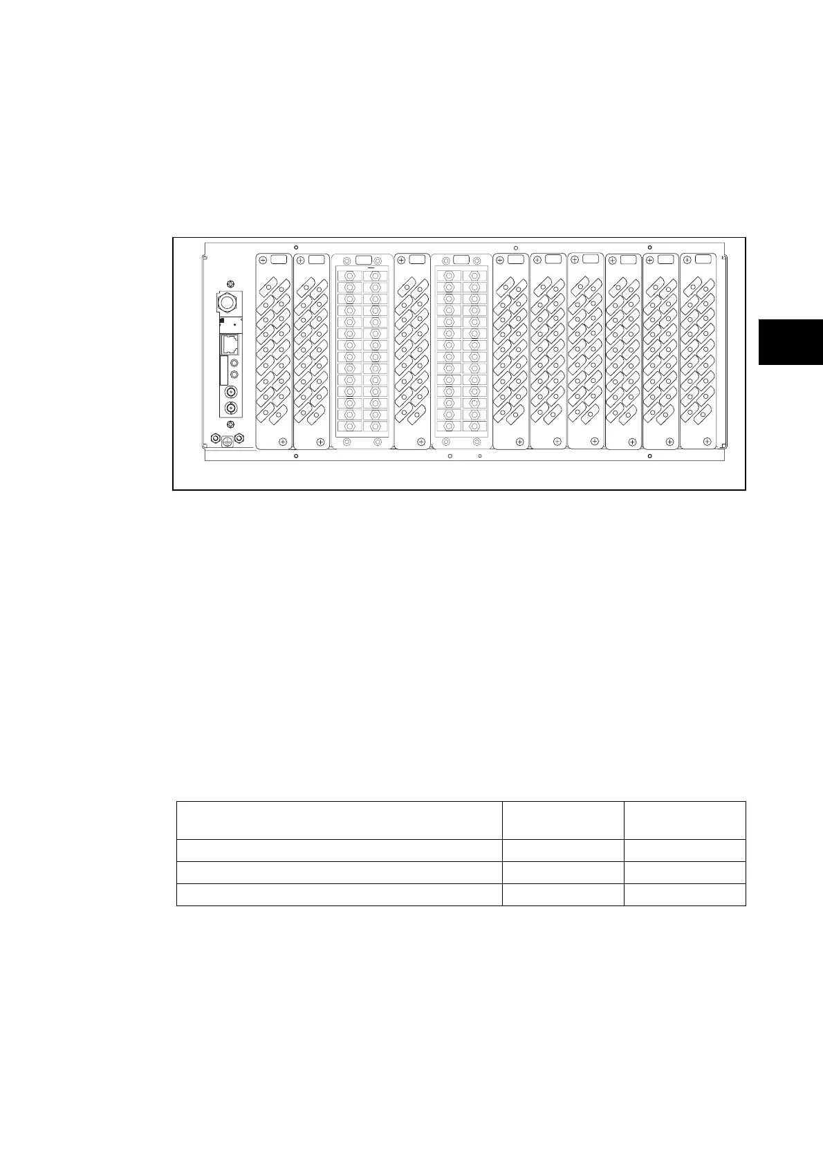
1.2.2 Relay rear panel
Examples of the rear panel of the relay are shown in Figure 2. All current signals, digital logic
input signals and output contacts are connected at the rear of the relay. Also connected at
the rear is the twisted pair wiring for the rear EIA(RS)485 communication port; the IRIG-B
time synchronising input is optional, the Ethernet rear communication board with copper and
fiber optic connections or the second communication are optional.
P3xxxENx
A
2
18
16
14
12
10
8
6
4
17
15
13
11
9
7
5
3
1
2
18
16
14
12
10
8
6
4
17
15
13
11
9
7
5
3
1
2
18
16
14
12
10
8
6
4
17
15
13
11
9
7
5
3
1
2
18
16
14
12
10
8
6
4
17
15
13
11
9
7
5
3
1
2
18
16
14
12
10
8
6
4
17
15
13
11
9
7
5
3
1
2
18
16
14
12
10
8
6
4
17
15
13
11
9
7
5
3
1
G
H
J
KL M
2
18
16
14
12
10
8
6
4
17
15
13
11
9
7
5
3
1
2
18
16
14
12
10
8
6
4
17
15
13
11
9
7
5
3
1
2
18
16
14
12
10
8
6
4
17
15
13
11
9
7
5
3
1
B
E
F
D
C
TX
RX
SK6
LINK
ACTIVITY
00.02.84.9F.FF.9000.02.84.9F.FF.90
R
2014809820148098
xWorks
IRIG-B12xIRIG-B12x
WindRiver
R
1
2
3
4
5
6
7
8
9
28
10
11
12
13
14
15
16
17
18
19
20
21
22
23
24
25
26
27
1
2
3
4
5
6
7
8
9
28
10
11
12
13
14
15
16
17
18
19
20
21
22
23
24
25
26
27
GS
A – IRIG B / Ethernet / COMMS G – Sigma Delta Opto Board
B – Opto \ high break H – Relay \ Opto \ high break
C – Opto \ high break J – Relay \ high break
D – Sigma Delta analogue input board K – Relay \ high break
E – Sigma Delta Opto Board L – Relay board
F – Sigma Delta analogue input board M – Power supply board
FIGURE 2: P746 RELAY REAR VIEW 80TE
Refer to the wiring diagram in ‘Installation Chapter’ (P746/EN IN) for complete connection
details.
1.3 Relay connection and power-up
Before powering-up the relay, confirm that the relay power supply voltage and nominal ac
signal magnitudes are appropriate for your application. The relay serial number, and the
relay’s current and voltage rating, power rating information can be viewed under the top
hinged cover. The relay is available in the following auxiliary voltage versions and these are
specified in the table below:
Nominal Ranges
Operative dc
Range
Operative ac
Range
24 - 48V dc 19 to 65V -
48 - 110V dc (30 - 100V ac rms) ** 37 to 150V 24 to 110V
110 - 250V dc (100 - 240V ac rms) ** 87 to 300V 80 to 265V
** rated for ac or dc operation
Please note that the label does not specify the logic input ratings. The P746 relays are fitted
with universal opto isolated logic inputs that can be programmed for the nominal battery
voltage of the circuit of which they are a part. See ‘Universal Opto input’ in the Firmware
section for more information on logic input specifications. Please note that the opto inputs
have a maximum input voltage rating of 300V dc at any setting.
Once the ratings have been verified for the application, connect external power capable of
delivering the power requirements specified on the label to perform the relay familiarization
procedures. Figure 2 and 3 indicates the location of the power supply terminals but please
refer to the wiring diagrams in the Installation section for complete installation details
ensuring that the correct polarities are observed in the case of dc supply.