Getting Started P746/EN GS/G31
MiCOM P746 (GS) 3-
5
GS
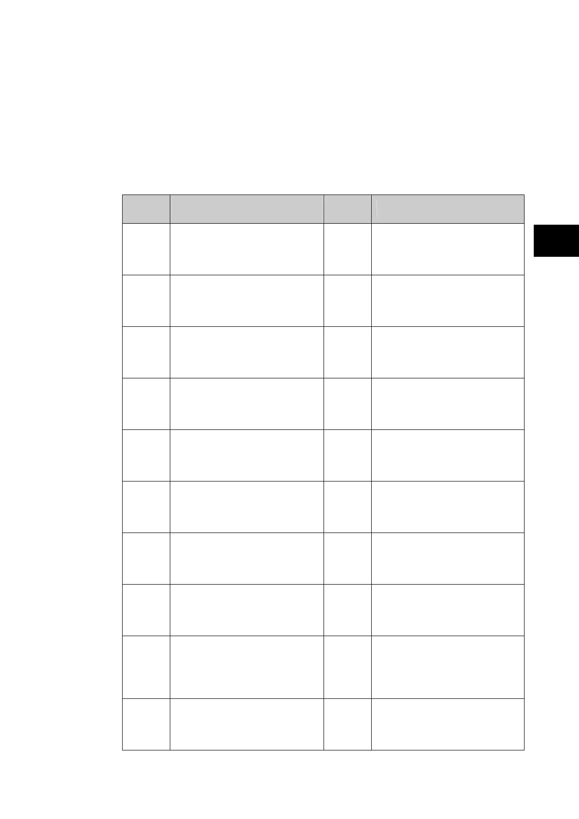
Programmable LEDs
All the programmable LEDs are tri-colour and can be programmed to indicate RED,
YELLOW or GREEN depending on the requirements. The 8 programmable LEDs on the left
are suitable for programming alarm indications and the default indications and functions are
indicated in the table below. The 10 programmable LEDs physically associated with the
function keys, are used to indicate the status of the associated pushbutton’s function and the
default indications are shown below:
The default mappings for each of the programmable LEDs are as shown in the following
table:
LED
Number
LED Input Connection/Text Latched P746 LED Function Indication
1
LED1 Red
LED1 Yellow
LED1 Green
Yes
CB1 closed
CB1 Alarm
CB1 open
2
LED2 Red
LED2 Yellow
LED2 Green
Yes
CB2 closed
CB2 Alarm
CB2 open
3
LED3 Red
LED3 Yellow
LED3 Green
Yes
CB3 closed
CB3 alarm
CB3 open
4
LED4 Red
LED4 Yellow
LED4 Green
Yes
CB4 closed
CB4 Alarm
CB4 open
5
LED5 Red
LED5 Yellow
LED5 Green
Yes
CB5 closed
CB5 Alarm
CB5 open
6
LED6 Red
LED6 Yellow
LED6 Green
No
CB6 closed
CB6 Alarm
CB6 open
7
LED7 Red
LED7 Yellow
LED7 Green
No
50BF Trip zone 1
87BB & 50 BF trip zone 1
87BB Trip zone 1
8
LED8 Red
LED8 Yellow
LED8 Green
No
50BF Trip zone 2
87BB & 50 BF trip zone 2
87BB Trip zone 2
9
FnKey LED1 Red
FnKey LED1 Yellow
FnKey LED1 Green
No
Zone 1: blocked
Zone 1: alarm (zone blocked but
not the CZ)
Zone 1: healthy
10
FnKey LED2 Red
FnKey LED2 Yellow
FnKey LED2 Green
yes
Zone 1: 87BB&50BF blocked
Not used
Zone 1: Test mode
 Loading...