Settings P746/EN ST/G31
MiCOM P746 (ST) 4-
11
ST
Setting Range
Menu Text Default Setting
Min. Max.
Step Size
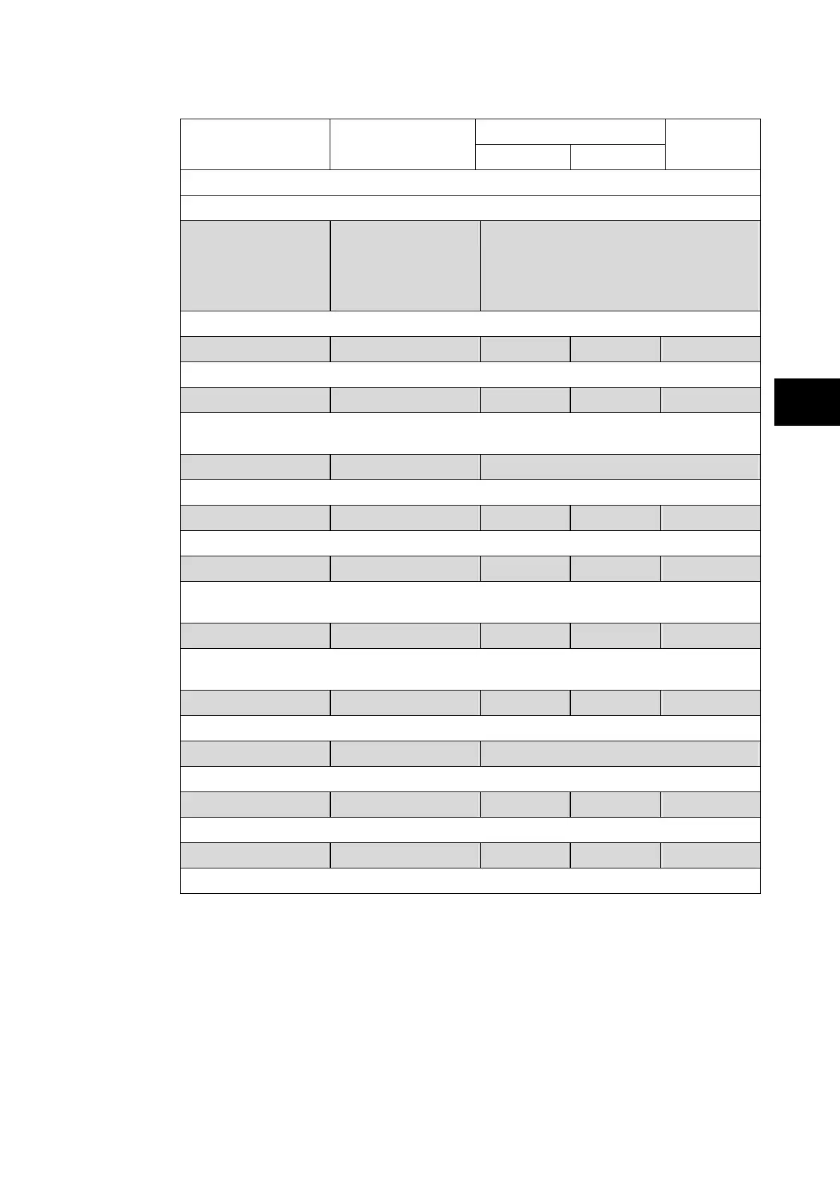
OVERCURRENT
TERMINAL 1 to 6 (one box) / TERMINAL 1 to 18 (three box)
I>1 Function IEC S inverse Disabled / US ST Inverse / US Inverse /
IEEE E Inverse / IEEE V Inverse / IEEEE
M Inverse / RI / UK Rectifier /UK LT
Inverse / IEC E Inverse / IEC V inverse /
IEC S Inverse
Setting for the tripping characteristic for the first stage overcurrent element.
I>1 Current 1.000 kA 80.00 A 4.000 kA 10 A
Pick-up setting for first stage overcurrent element
I>1 Time Dial 1.000 0.010 100.0 0.010
Setting for the time multiplier setting to adjust the operating time of the IEEE/US IDMT
curves.
I>1 Reset Char DT DT / Inverse
Setting to determine the type of reset/release characteristic of the IEEE/US curves.
I>1 tReset 0.000 s 0.000 s 100.0 s 10.00 ms
Setting that determines the reset/release time for definite time reset characteristic.
I>1 k(RI) 1.000 0.100 10.00 0.050
Selects the electromechanical inverse time curve (RI) curve K value from 0.100 to 10 for
the first stage of phase overcurrent protection
I>1 TMS 1.000 0.025 1.200 0.025
Setting for the time multiplier setting to adjust the operating time of the IEC IDMT
characteristic
I>1 Time Delay 1.000 s 0.000 s 100.0 s 10.00 ms
Setting for the time-delay for the definite time setting if selected for first stage element
I>2 Function Disabled Disabled / DT
Setting for the second stage overcurrent element.
I>2 Current 1.000 kA 80.00 A. 32.00 kA 10 A
Pick-up setting for second stage overcurrent element.
I>2 Time delay 1.000 s 0.000 s 100.0 s 10.00 s
Setting for the operating time-delay for second stage overcurrent element.