www.scheppach.com / service@scheppach.com / +(49)-08223-4002-99 / +(49)-08223-4002-58
GB
|
23
• The product is intended solely for use at connection
points that
a) do not exceed a maximum permitted supply
(400V)), or
b) have a continuous current-carrying capacity of
the mains of at least 100 A per phase.
• As the user, you are required to ensure, in consulta-
tion with your electric power company if necessary,
that the connection point at which you wish to oper-
ate the product meets one of the two requirements,
a) or b), named above.
Damaged electrical connection cable
The insulation on electrical connection cables is of-
ten damaged.
This may have the following causes:
• Passage points, where connection cables are
passed through windows or doors.
• Kinks where the connection cable has been im-
properly fastened or routed.
• Places where the connection cables have been cut
due to being driven over.
• Insulation damage due to being ripped out of the
wall outlet.
• Cracks due to the insulation ageing.
Such damaged electrical connection cables must not
be used and are life-threatening due to the insula-
tion damage.
Check the electrical connection cables for damage
regularly. Make sure that the connection cable does
not hang on the power network during the inspection.
Electrical connection cables must comply with the
applicable VDE and DIN provisions. Only use con-
nection cables with the marking „H07RN“.
The printing of the type designation on the connec-
tion cable is mandatory.
For single-phase AC motors, we recommend a fuse
rating of 16A (C) or 16A (K) for machines with a high
starting current (starting from 3000 watts)!
AC motor 230 V~ / 50 Hz
Mains voltage 230 V~ / 50 Hz.
Mains voltage and extension cables must be 3-lead
= P + N + SL. - (1/N/PE).
Extension cables must have a minimum cross-sec-
tion of 1.5 mm².
Mains fuse protection is 16 A maximum.
Three-phase motor 400 V~ / 50 Hz
Mains voltage 400 V~ / 50 Hz
Mains voltage and extension cables must be 5-lead
(3P + N + SL (3/N/PE).
Extension cables must have a minimum cross-sec-
tion of 1.5 mm².
Mains fuse protection is 16 A maximum.
• Undo the star grip screw (10a)
• Push the stroke set rod (8) to the top until it is
stopped by the spring
• Tighten the star grip screw (10a) again.
• Switch motor on
• Check upper position
Switching on and o (12)
Press the green button for switching on.
Note: Check the function of the ON/OFF unit before
Restarting safety in case of current interruption
(no-volt release).
In case of current failure, inadvertent pulling of the
automatically.
For switching on again, press anew the green button
of the switch unit.
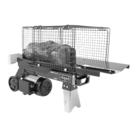
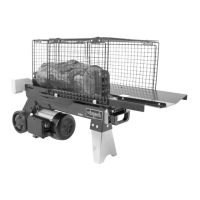
Splitting
• Place the log on the table, hold it with both handles,
press the handles down. As soon as the splitting
knife enters the wood, push the handles down and
to the outside at the same time. This prevents the
wood from putting pressure on the holder plates.
• Only split straight cut logs.
• Split the logs in vertical position.
• Never split in horizontal position or across.
• Wear protective gloves when splitting.
Attention! The lateral tray tables may not be used as
splitting support or splitting table.
End of work
• Move the splitting knife to the lower position.
• Release one operating arm.
•
• Close the venting cap.
• Observe the general maintenance instructions.
11. Electrical connection
The electrical motor installed is connected and ready
for operation. The connection complies with the ap-
plicable VDE and DIN provisions.
The customer‘s mains connection as well as the ex-
tension cable used must also comply with these reg-
ulations.
• The product meets the requirements of EN 61000-
3-11 and is subject to special connection conditions.
This means that use of the product at any freely se-
lectable connection point is not allowed.
• Given unfavourable conditions in the power supply
-
porarily.
 Loading...