www.scheppach.com / service@scheppach.com / +(49)-08223-4002-99 / +(49)-08223-4002-58
32
|
GB
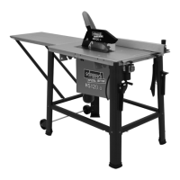
3. Slide the connected guide rails to the left until the
rip fence is at the outer right side of the saw blade.
4.
5.
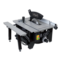
8.4 Mounting / dismounting the Saw Blade
Guard (Fig. 13 + 14)
1. Loosen the screw with nut and washer (27)of the
saw blade guard (2). Place the saw blade guard
(2) from the top onto the riving knife (3).
2. Mount the screw with nut and washer (27) so that
3. Do not overtighten the bolt (27) The saw blade
4. Dismantling is carried out in reverse order.
m CAUTION:
guard (2) has to be lowered onto the item being sawn.
then release it. The saw blade guard should automat-
8.5 Mounting / adjusting the riving knife;
Caution! Remove the mains plug! The setting of
the saw blade (4) must be checked whenever a
blade has been replaced.
1. Adjust the saw blade (4) to a max. cutting depth,
move to the 0° position and lock in place.
2. Dismantle the saw blade guard (2) (not during in-
3. Release the two countersunk screws of the table
insert (25) and remove the table insert (5).
4.
the open-ended spanner AF8 supplied).
5. Push the riving knife (3) upwards.
6. The distance between the saw blade (4) and riv-
ing knife (3) should be between 3 mm and max. 5
mm, (Figure. 18)
7.
and mount the table insert (5).
8. Mount the saw blade guard (2) with the screw and
knurled nut and washer (27).
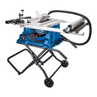
8.6 Connect the suction device (Fig. 2)
1. Attach a suction hose to the suction adapter (16).
adapter (16).
2. A household vacuum cleaner is not suitable as
a suction device. Use a multi-purpose vacuum
cleaner or a swarf extraction machine.
Hexagon screws must each be inserted from outside
inwards, and the connections must be secured from
be erected in a correct and stable manner.
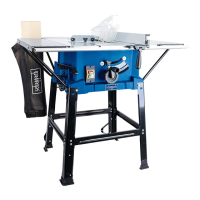
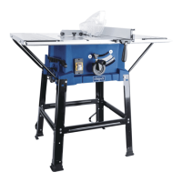
8.1 Assembling the frame and table width extend-
er (Fig. 4-10)
1. Turn the table circular saw over and place it on
2.
saw table (1) using the hexagon bolts (a), washer
(c), spring washer (d) and nuts (e). (Fig. 6)
3. Screw the four legs (19) and the table supports (24)
onto the housing. (Fig. 7)
4.
table width extender (6) using hexagon bolts (a),
washer (c), spring washer (d) and nuts (e). Loose-
onto the housing using the hexagonal bolts (a).
5.
with the legs (19) using the carriage bolts (b),
washer (c), spring washer (d) and nuts (e). (Fig. 8)
6. Screw the stand brackets (22) to the holes in the
-
riage bolts (b), washers (c), spring washers (d)
and nuts (e). (Fig. 9)
7. ATTENTION: Both stand brackets (22) must be
points (23). (Fig. 9)
8. Align the table width and length extension lush
with the saw table.
9. Next, tighten all the screws of the legs (19) and
the table width extender (6).
10. Now attach the rubber feet (21) to the legs (19)
(Fig. 10).
11. Place the table circular saw on the base frame (11).
8.2 Insert guide rail (Fig. 11+12)
1. Mount the carriage bolts (b) in the holes provided
2.
3. Connect both guide rails (15, 15a).
4. Slide the connected reails over the guide groove
are centred on the table surface.
8.3 Aligning the guide rail (Fig. 11+12)
1. Turn the saw blade out of the sawing table at
far as it will go.
2. Position the rip fence (14) with the cam lever (13)
open on the guide rails (15) on the sawing table
 Loading...