Page 5.6
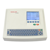
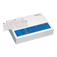
SCHILLER AT-2 6-Channel ECG Unit
SERVICE HANDBOOK Issue 2.1 November 1998
Chapter 5
Adjustments
Battery Charge Voltage
Precautions and Requirements
The unit must be placed on an antistatic mat and antistatic precautions observed when any
maintenance is carried out on the AT-2. The room temperature should be between 18 and 28
degrees.
Tools and Equipment
Digital voltmeter
Small flat bladed screwdriver
Resistor 2.7 kOhms, 250 mW
Procedure
The battery charge voltage is nominally 13.5 V. Adjust and check as follows:
DISCONNECT THE MAINS SUPPLY
CAUTIONS
THE AT-2 CONTAINS STATIC SENSITIVE CMOS COMPONENTS; OBSERVE
ANTISTATIC PRECAUTIONS . PLACE THE UNIT ON AN EARTHED ANTISTATIC MAT.
PERSONNEL MUST BE EARTHED WHEN HANDLING THE UNIT.
EXERCISE CARE WHEN REMOVING AND REPLACING CONNECTORS. NEVER USE
FORCE. NEVER STRAIN THE CABLE ASSEMBLIES.
Disassemble the unit as detailed in Chapter 4 and remove Printer and printer tray assembly.
Remove the Main board MK 12-1 from the assembly and remove the microprocessor
EMC shield from the board
Replace the board in position
Remove the two battery connectors (if not already removed) and connect a 2.7 kOhm 250
mW resistor across the two battery connectors on the main board to simulate a discharged
battery. Connect the digital multimeter across the resistor.
WARNING
EXERCISE CARE - BE AWARE THAT POTENTIALLY LETHAL VOLTAGES ARE
PRESENT
Connect the Mains supply.
Adjust VR1 to obtain a charging voltage of 13.5V.
Disconnect the mains supply and reassemble the unit as detailed in Chapter 4.