Page 5.8
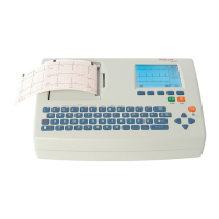
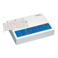
SCHILLER AT-2 6-Channel ECG Unit
SERVICE HANDBOOK Issue 2.1 November 1998
Chapter 5
Adjustments
ECG Amplifier +2V, -2V and PWM Ramp Time Adjustment
The ±2 V voltage rails generated on the ECG Amplifier board are used as a reference by the
measurement and PWM (Pulse Width Modulation) circuits.
Note: The ECG board reference voltage is given on the service printout and can be checked
without disassembling the unit. Full details of the service printout are given later in this chapter.
IMPORTANT
THE ±2 V REFERENCE VOLTAGES, AND THE PWM RAMP MUST BOTH BE ADJUSTED
AT THE SAME TIME.
Tools, Equipment and Material
Digital voltmeter
Small flat-bladed screwdriver
Procedure
DISCONNECT THE MAINS SUPPLY
CAUTIONS
THE AT-2 CONTAINS STATIC SENSITIVE CMOS COMPONENTS; OBSERVE
ANTISTATIC PRECAUTIONS . PLACE THE UNIT ON AN EARTHED ANTISTATIC MAT.
PERSONNEL MUST BE EARTHED WHEN HANDLING THE UNIT.
EXERCISE CARE WHEN REMOVING AND REPLACING CONNECTORS. NEVER USE
FORCE. NEVER STRAIN THE CABLE ASSEMBLIES.
Disassemble the unit as detailed in Chapter 4 and remove the Printer tray assembly.
Remove the Main board MK12-1 from the assembly and remove the microprocessor EMC
shield from the board
Replace the board in position
Reconnect the keyboard to the control board and place the top assembly on its side in front
of the Base assembly .
ECG Amplifier reference voltage
Switch the unit on and measure the voltage difference between the +2 V reference and the -
2 V reference on pins 1 and 7 of operational amplifier U5. Adjust trimmer VR2 to achieve
a voltage difference of 4000 mV ±2mV.
Obtain a printout of the test screen by pressing
ALT - 0 - 3 - any number 0...6
Ensure that the Uref+ and the Uref- measurements are both 2000mV ± 20mV. Ensure that the
Udiff reading is 4000mV . Adjust VR3 to achieve a Udif reading of 4000mV + 20mV.
Reassemble the unit as detailed in Chapter 4. Re-check the voltage by again obtaining a
service printout.