Overview|Operational status and fault indication
B-HB-0133EN Operating panel Integral MAP|User manual 13
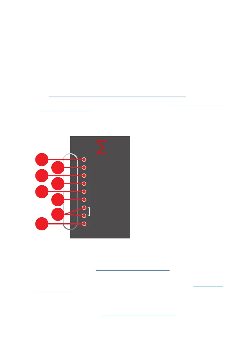
3.3.3.5 Freely programmable buttons and LED
(Depends on software version)
There are buttons
L
,
b
, and LEDs
M
,
c
, which can be freely programmed and labelled
on the operating panel as customers wish. Fire protection equipment feedback must be
parameterised at the LED
c
according to EN54-2 chapter 7.10.3.
3.3.4 Element states and operation
Element states and addition information can be called up in two different ways:
• Calling up the element either via the element number or the element type (buttons
N
–
Q
) (Chapter Select elements and querying element states, Page21)
• Calling up the state and information of an element in a list (Chapter Alarms, faults and
additional lists, Page19)
3.4 Operational status and fault indication
|Operational status and fault indication
Operation
Faults
System
Power
Disablements
Test Mode
Fire protection
equipment
Call Service
The Operation
h
LED indicates the system’s current operating status. The LED is not lit
in case of power failure, control panel failure and deactivated control panel acoustics.
The Faults
i
LED flashes, if there is a fault. The LED lights up if there is a control panel
failure. Further Information: Chapter Fault messages, Page20
The System
j
LED flashes in addition to the faults LED
i
, if there is a module fault.
The LED lights up if there is a control panel failure. Further Information: Chapter Fault
messages, Page20
The Power
k
LED flashes in addition to the faults LED
i
, if a fault with the emergency
power supply either a mains fault (power failure) or a battery fault (battery defective) is
detected. Further Information: Chapter Fault messages, Page20
The Disablements
U
LED lights up, if at least one system element is disabled.