specified maximum tightening torques (see chapter "Torque
per screw" ( 4, Page 16)). Then check again for radial and
axial runout (see Fig. "Assembly of the chuck" - E).
The obtainable radial and axial runout accuracies depend on the
outer diameter of the chuck.
The radial and axial runout tolerance correspond to the technical
delivery specifications for chucks according to DIN ISO 3442-3.
Mounting the ROTA NC plus / NCF plus chuck with a centering
edge
Remove cylindrical screws of the top jaws together with the T-nuts
(Item 46).
Move the draw tube to the frontmost position by actuating the
clamping cylinder.
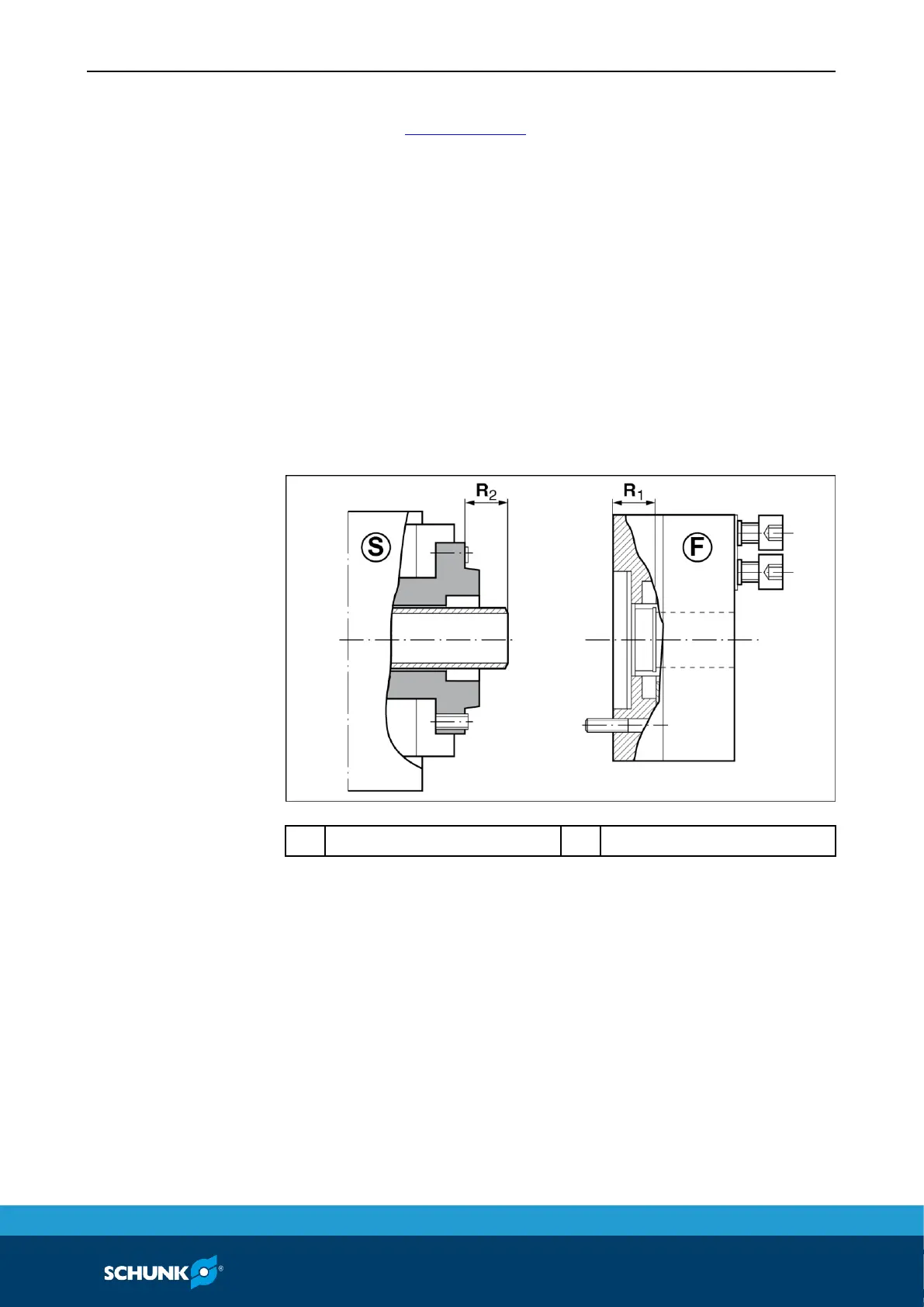
Attachment
Cylinder piston in frontmost position
R1 = press chuck piston into frontmost position and measure with
a depth gauge.
R2 = R1 – 0.5 mm (max. – 1 mm)
Chucks in sizes 185 and 215
• The entire chuck must be turned to the draw tube (rod).
Chucks in sizes 260 and 315
• Unscrew the cylindrical screws (Item 28) and pull out the center
sleeve (Item 4).
 Loading...