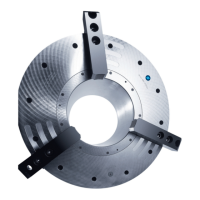
TBS, TBS-LH stationary power chucks
54 02.00|0889073_ROTA TB-TBS-EP |en
Disassembly and assembly
The item numbers specified for the corresponding individual
components relate to chapter drawings.( 16, Page 64)
TB 400 - 850, TB-LH 400 - 850, TB/TB-LH 1000 (year of
construction 2010 or later)
Disassembly
1 Unscrew both the pneumatic quick coupling pieces from the
distributor ring (8), then detach the distributor ring (8) from
the spindle nose together with the mount. Screw in the eye
bolt (thread on circumference of chuck body) and mount using
a cargo crane. Undo the chuck mounting screws (24) and lift
the chuck off the spindle nose.
2 Remove both profile ring seals (47) from the distributor ring
(8) and check for wear.
3 Carefully unscrew the locking screw (15) and remove the pilot-
controlled non-return valve system and O-ring (37).
The valve system (13) must be removed before proceeding with
4 Check all the O-rings in the valve system for wear and replace
them if necessary.
5 Unscrew the hexagon socket screws (23) from the chuck
mount (7), then screw 3 of them into the threaded extraction
holes provided and use them to extract the mount. Remove
the mount and O-rings (39,44).
6 Undo the hexagon sockets screws (25) that connect the piston
cover (6) to the piston (3).
7 Screw three hexagon socket screws into the threaded holes on
the piston cover (6) and extract the piston cover (6) from the
piston (3).
8 On the front side of the chuck, undo the hexagon socket
screws (20) on the bushing (4) and pull out the bushing (4)
from the front, tapping it lightly from the back of the chuck to
move it forward.