20 02.00|0889073_ROTA TB-TBS-EP |en
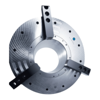
Clamping force / speed diagrams
The diagrams refer to 3-jaw-chuck.
Clamping force/speed curves were determined with hard standard
stepped jaws SHB, SWB and SWB-AL. The maximum actuating
force was introduced and the jaws were placed flush with the base
jaw outer edge.
The chuck is in perfect condition and lubricated with SCHUNK LINO
MAX special grease.
Should one or several of the above mentioned parameters be
changed the diagrams are no longer valid.
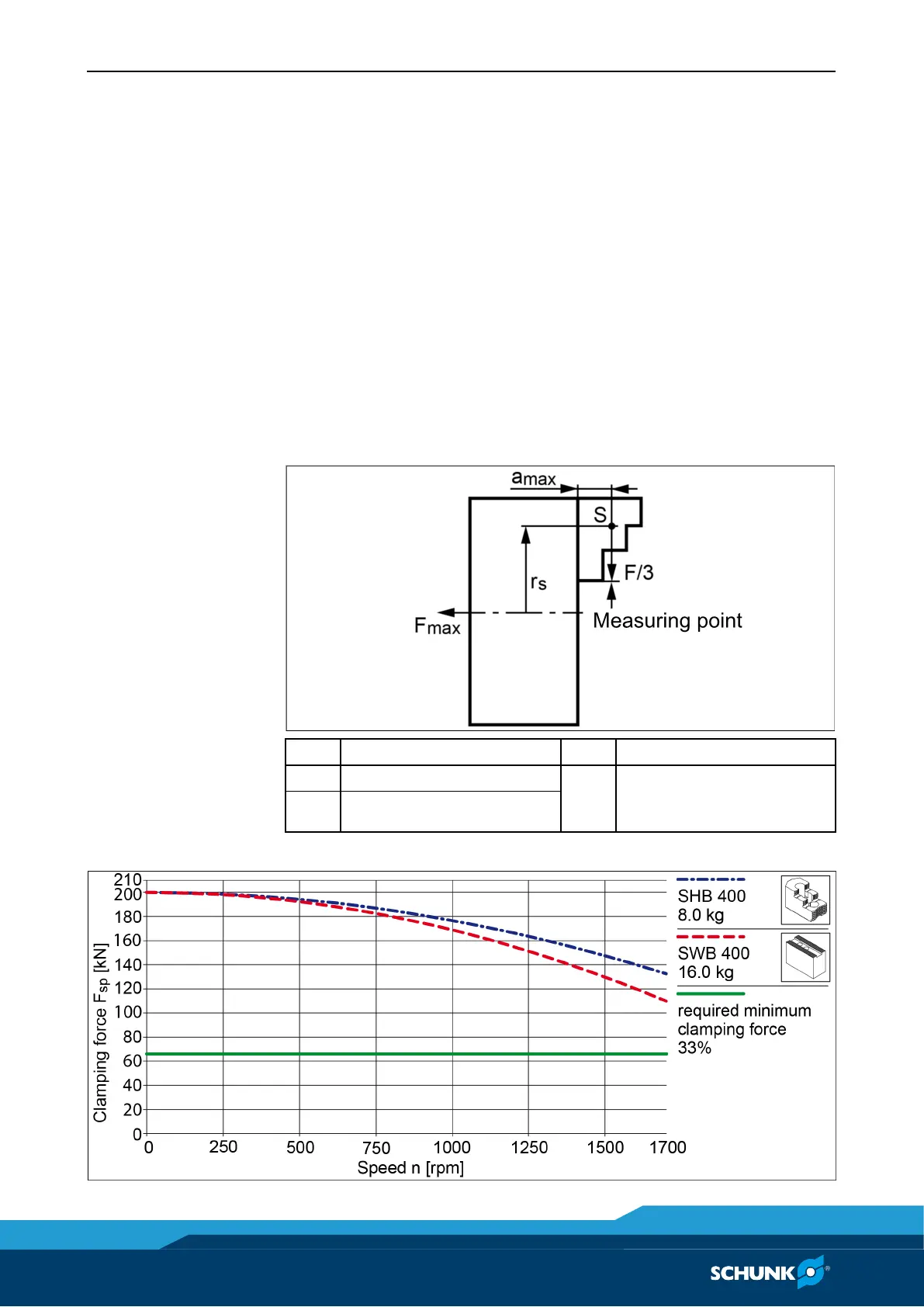
Chuck set-up for clamping force / speed diagram
max
center of gravity in axial
max
Clamping force-RPM-diagram ROTA TB 400-115