Date Code 20210715 SEL-2890 Instruction Manual
Installation
Initial Checkout
2.3
prompt indicates that you are in a Console session Level 1. During a
Console session the user communicates with, and NOT through, the
SEL-2890. Use the SHO command to view the settings.
Step 3. All settings modifications can be made from the serial port. At this
time, we are just interested in the minimum number of settings that
will allow you to install the SEL-2890 on your network. A detailed
description on an individual setting basis is given in Section 3:
Settings and Commands. For this step, information will be needed
from your network administrator. SEL recommends that your
network administrator review the settings options obtained from the
SHO command. The settings IP, SUBNET_MASK, and GATEWAY
need to be obtained before the transceiver is available on your
network. The serial data rate in the SEL-2890 can be set to match the
target SEL relay or communications processor that will communicate
with the transceiver.
Step 4. At the Level 1 prompt, #>, gain Level 2 access by issuing a 2AC
command followed by the Level 2 password. See PASSWORD on
page 3.12 for default password information. After issuing the SET
command, press <Enter> to scroll down through the settings. Enter
the serial port data rate (optional) and IP address that you obtained
from your network administrator when prompted for these settings.
Continue on with the settings for SUBNET_MASK and GATEWAY.
Repeat the carriage return to obtain the “Save (Y/N)” question. Save
your settings. The Console session will be closed after you save your
settings. You can also use the EXIT command to close the Console
session.
Initial Checkout
Step 1. After following the steps for installation, your SEL-2890 is ready to
be connected to an SEL relay or communications processor. Verify
that the proper relay or communications processor’s jumpers have
been installed to enable serial port power. Refer to the respective SEL
manuals to locate serial port jumper positions. Once port power is
enable on the SEL equipment, connect the SEL-2890.
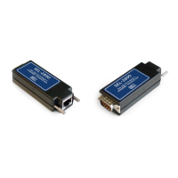
Step 2. Plug the SEL-2890 into the network by using a standard Unshielded
Twisted Pair (UTP) or Shielded Twisted Pair (STP) Ethernet cable
with RJ45 connectors. Verify that the green (Link) LED is
illuminated on the SEL-2890. If not, check cable, connections, and
hub or switch. After the green link light is illuminated, use the PING
command to confirm that the SEL-2890 is available on the network.
The PING command can be accessed by starting a command line
session from the standard Windows Run window as shown below.