Service Manual
Remote Control Cable/Radio
577
9. Monitoring-, Warning-, and
Control Elements
2
3
4
5
6
1
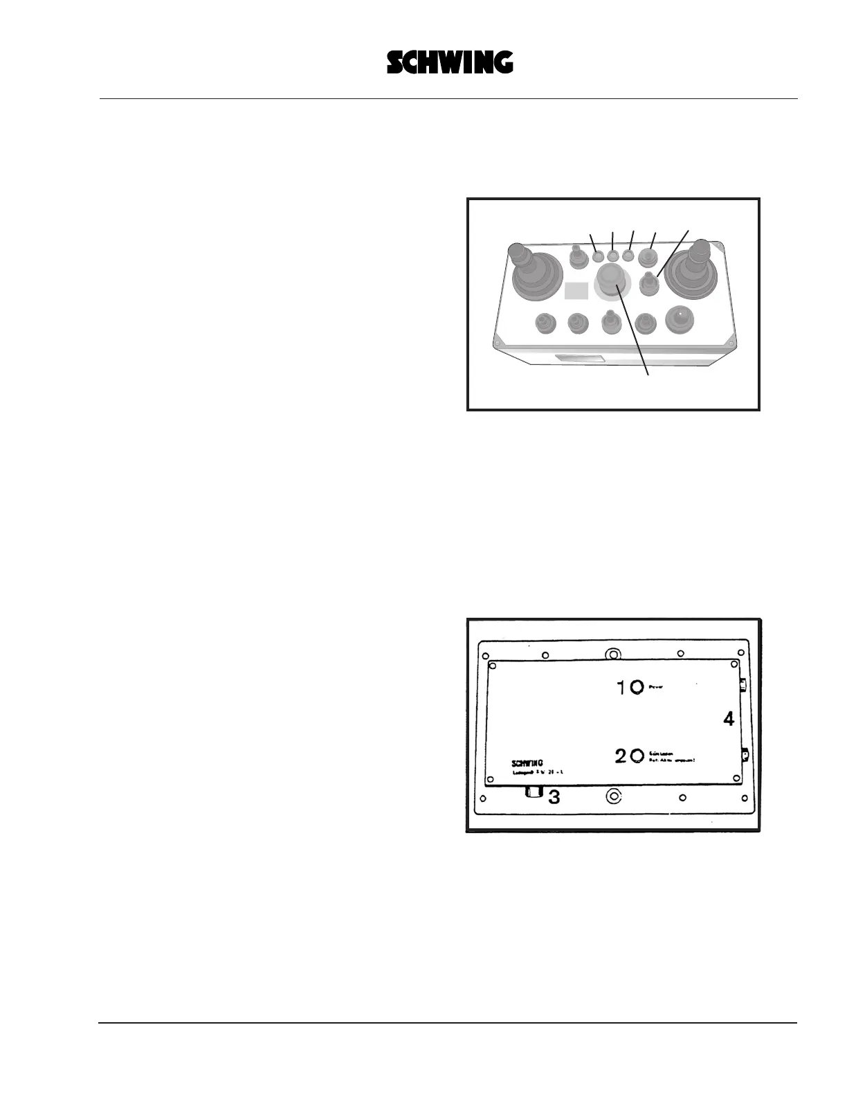
TRANSMITTER (fig. 1)
1- EMERGENCY SHUT-OFF button
2- LED: battery voltage monitoring
3-LED: Transmitter signal output monitoring
4-LED: EMERGENCY SHUT-OFF
5- Selector switch: transmitter power supply
ON/OFF
6-Selector switch: transmitter channel selection
HF1/HF2
The other monitoring-, warning- and control
elements correspond to those of the cable control
units of the coresponding machine.
BATTERY CHARGER (fig. 2)
1-LED: battery charger power supply ON
2- Bi-coloured LED
green LED
red LED
3-Socket outlet: power supply
4-Battery compartment
fig. 1
fig. 2
= battery is being charged
= battery not correctly
inserted - change polarity
 Loading...