Service Manual
Remote Control Cable/Radio
578
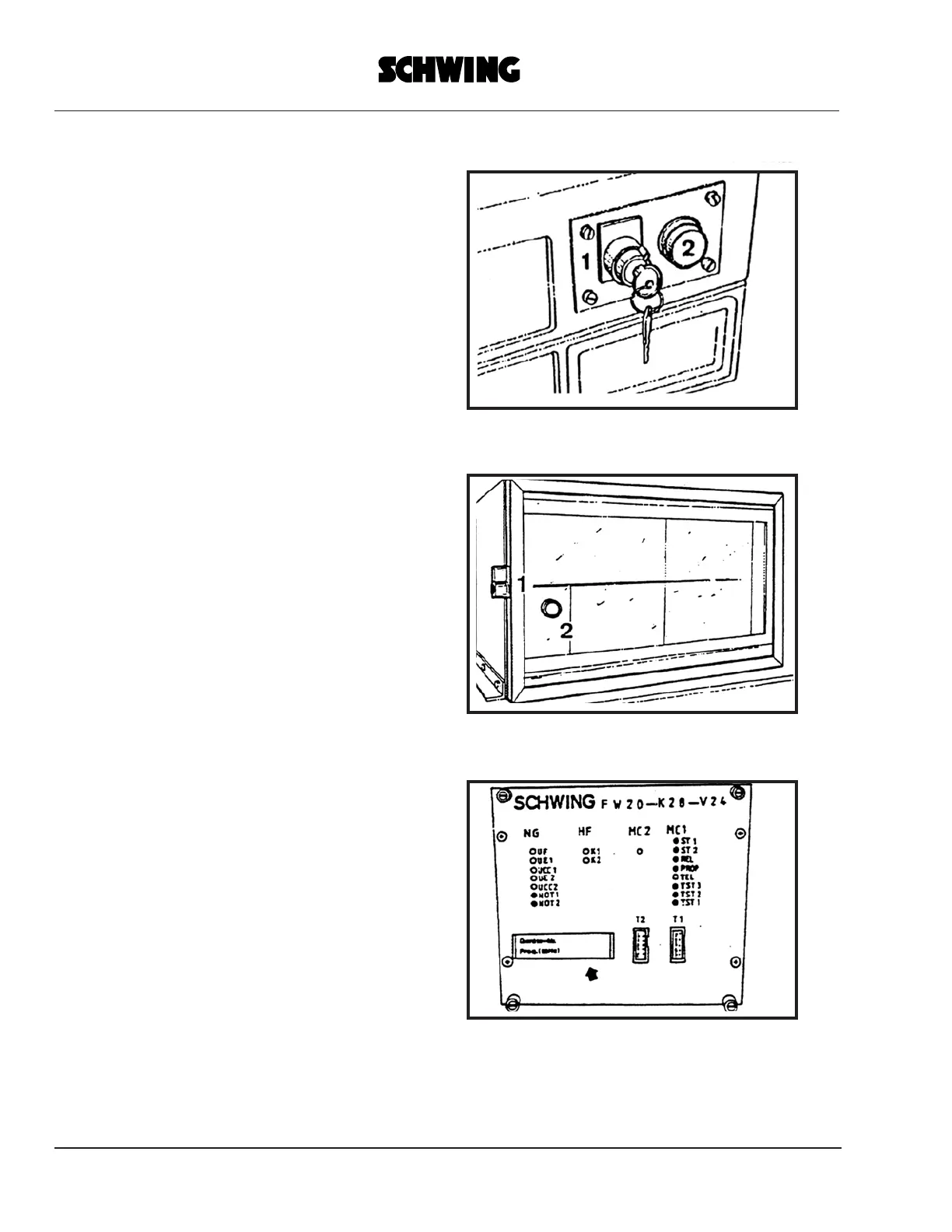
RECEIVER POWER SUPPLY (fig. 1)
1- Key switch in driver’s cab: power supply ON
2- Pilot lamp: power supply ON
INSTALLATION OF RECEIVER (fig. 2)
1-Cover lock
2-Pilot lamp: power supply ON
RECEIVER (fig. 3)
T1-Connector for diagnostic unit
T2-Connector for diagnostic unit
fig. 1
fig. 2
fig. 3
 Loading...