Service Manual
Remote Control Cable/Radio
601
"MULTI-Control" system"
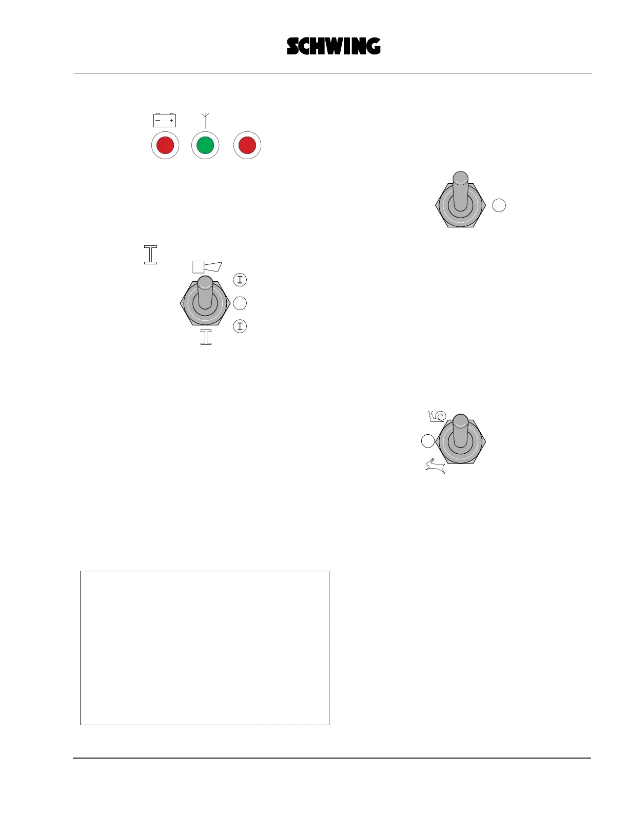
The green LED 2 (antenna) is lit up
continuously and the red LED 3 is flashing.
Enable the control system by setting switch
6 briefly to
Only then will the red diode (LED 3) go out
and the green one will flash.
The transmitter is now ready for operation
and the commands given with the control
elements are executed by the concrete
pump.
"COMFORT-Control" system:
The red diode (LED 3) goes out and the
green one (LED 2) is lit up.
The transmitter is now ready for operation
and the commands given with the control
elements are executed by the concrete
pump.
Note:
The "COMFORT-Control" system does not
provide an enabling function for switch 6.
Switch 6 is needed for a fault-
acknowledging function labeled "quitt"
[acknowledge].
See also the abbreviated "COMFORT-
Control" operating instructions, i.d. no.
10167123.
To switch off the transmitter, e.g. after the
work has ended,
set the "Power" switch 5 to
neutral position ("0").
Do not depress the EMERGENCY SHUT-
OFF button for normal shut-off to prevent
the emergency shut-off signal from being
transmitted permanently and the
rechargeable battery from being emptied.
Special transmitter operation features
1. Selecting the boom speed
The boom control functions must be
activated
with switch 6.
In the center position ("0") of this switch all
functions of the boom are deactivated.
Moving the joysticks causes the red diode
(LED 3) to light up to indicate that boom
operation is disabled.
The switch must be set to the "Snail" or
"Hare" symbol.
"Snail" = slow is the preferred speed for
normal working operation and
"Hare" = fast is the speed used for setting
up of the placing boom.
POWER
HF1
HF2
Stop
123
0
0
0