Service Manual
Remote Control Cable/Radio
560
8. Control and Monitoring
Equipment
Radio Remote
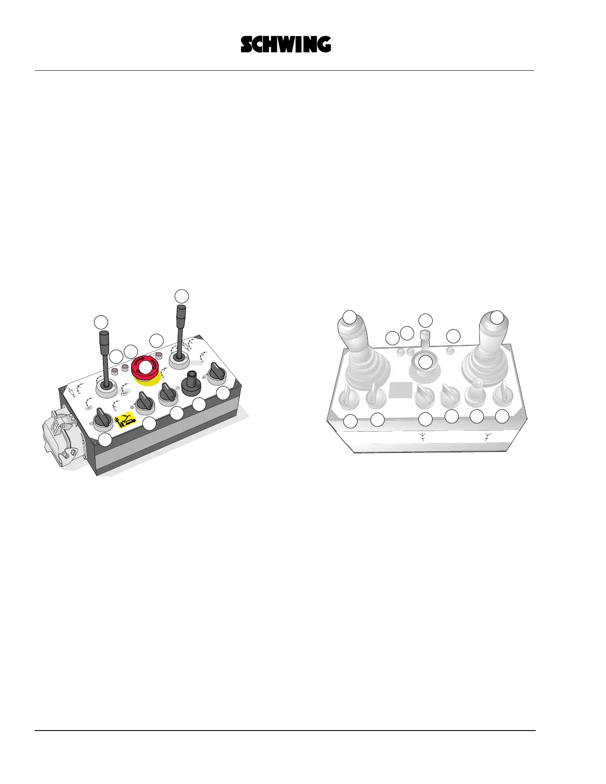
Figure 1 = Black-and-white transmitter
Figure 2 = Proportional transmitter
1 - Control lever with spring-centered 0-position
for placing boom functions
2 - see 1
3 - EMERGENCY OFF button
4 - Potentiometer: output adjustment of concrete
pump
5 - Antenna socket with removable antenna
6*- Selector switch: vibrator on/off
7*- Button: horn on truck
8 - LED: EMERGENCY OFF button operated
9 - Selector switch: truck engine speed adjustment
10*- Selector switch: engine on/off
11- Selector switch: concrete pump (pumping - off
- reverse)
12- LED: battery charge monitor
13- LED: radio signal output monitor
14- Selector switch: transmitter power supply ON/
OFF
* = Optional extra
8
9
14
13
12
10
11
4
3
2
1
8
9
14
13
12
10
11
46
4
5
2
1