LOCK
Your Elite Snack Vendor has one Lock, more commonly known as a "T" handle Lock. To unlock the Front Panel, insert key and
turn clockwise ¼ turn. When unlocked the "T" of the Lock will pop out from the vendor. Turn ¼ turn clockwise to open Front
Panel.
MOUNTING
Your Elite Snack Vendor can be mounted to either an optional Stand or to the Elite Beverage Vendor.
The optional Stand comes pre-assembled, with mounting hardware. You will need tools for mounting.
1. To Mount to optional Stand.
A. Unlock and open Stand.
B. Set vendor on top of Stand.
C. Unlock and open Front Door.
D. Remove bottom Product Tray. Pull Product Tray fully forward,
keeping it level.
E. Lift Product Tray to release from the track. Then it can be pulled
forward and lifted out.
CAUTION: The Product Tray Wire Harness will need to be unplugged prior to complete removal of the Product Tray. The Wiring
Harness is plugged into the inside right-hand side of the vendor. You may need assistance.
F. Set back of Product Tray into Vend area, steady it with one hand, and disconnect the Wiring Harness.
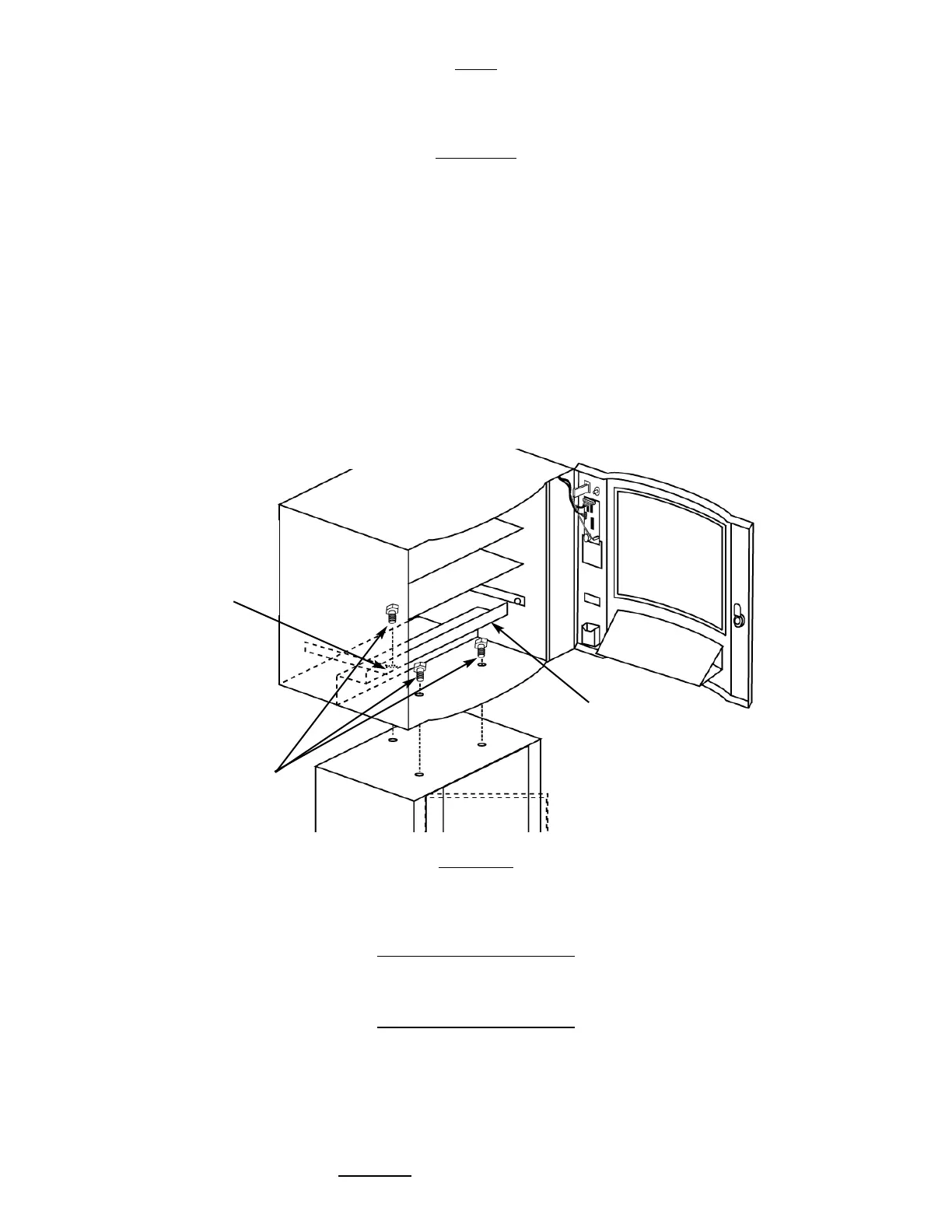
G. Attach Stand to bottom of vendor. Insert 3 bolts down through the vendor into welded nuts in the top of the Stand.
Tighten. (Fig. 1)
Mounting to the optional Elite Beverage Vendor will be explained in that section of the Manual (Pg. 20)
LEVELING
Once your vendor is in its new location, you will need to level it to insure proper operation. You will need a level. We recommend
a 3ft(1m) level, as it will give a more accurate reading than a small torpedo level. There are threaded Levelers included with your
vendor. These Levelers screw into the bottom of your Stand and can then be adjusted up or down as needed.
ELECTRICAL
CONNECTION
The Elite Snack Vendor requires one (1) 120 VAC grounded outlet for each vendor(s).
Elite Snack Vendor 120 Volts Less than 1 Amp
KEYPAD AND LED DISPLAY
The Keypad (Fig. 2) is a touch sensitive operation. Light pressure will be necessary to activate each number or letter. The ven-
dor's Keypad is used by the customer to make their selection, and by the operator to set and test many functions of the ven-
dor.
The LED Display shows the customer the amount of money entered into the vendor, and the cost of their selection, it shows the
operator the Service Mode functions for setting and testing the various functions of the vendor.
1. To Access Operator Functions:
A.) Unlock and open the Front Door to access the Circuit Board, and
enter Service Mode by pressing the Red Service Mode Button. (Fig. 3)
Figure 1 Optional Stand Mount
Rear hole is
hidden
behind the
Anti-Theft
Wall
Anti-Theft
Wall
Bolts