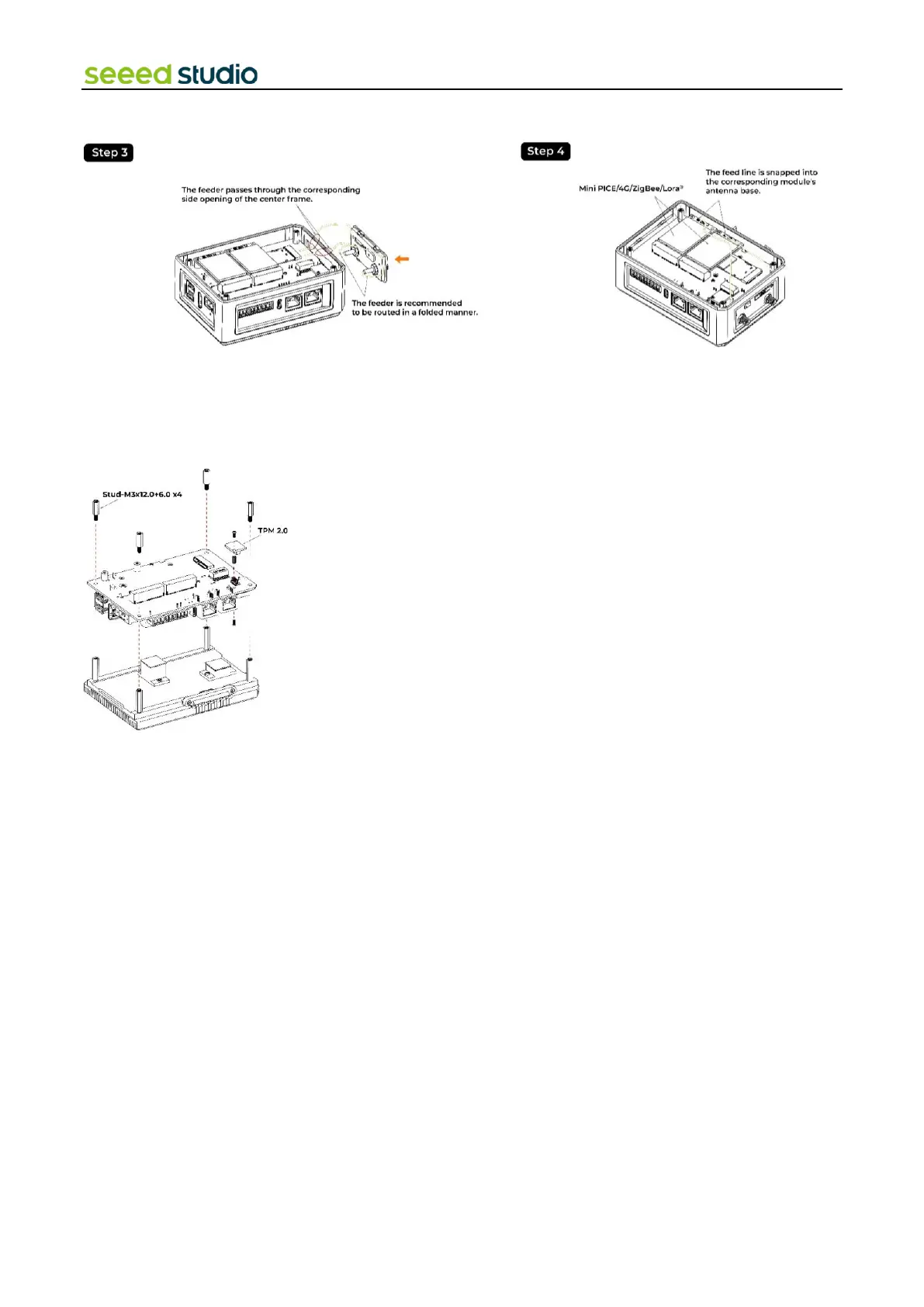
4.5 Assemble TPM 2.0 Module
Step 1: Remove the back cover following the disassembly guide.
Step 2: Load the TPM 2.0 module into the J13 socket.
4.6 Assemble UPS and PoE module
Step 1: Before installing the UPS and PoE module on the CM4 module side of board, disassemble the entire device following
the disassembly guide provided.
Step 2:
⚫ Using two PM2.0xL5.0 screws and M2.0x5.0 standoffs, secure the UPS module onto two holes without metal contact pads.
⚫ Make sure the UPS module is aligned properly and firmly attached using the provided screws and standoffs.
Step 3: Install the PoE Module
⚫ Align the PoE module with the designated aperture on the board.
⚫ Carefully solder the PoE module onto the board. Due to the compact nature of the board, exercise caution while soldering
to avoid damaging nearby components.