REPLACEMENT PROCEDURE
This procedure requires the following tools: Phillips screwdriver for the M4 screws, 1.5 mm hexagonal wrench,
11-12 mm monkey wrench, nipper, cutter, wire stripper, soldering iron, industrial dryer and heat-shrinkable tube.
1
Using a soldering iron - desolder the 3 wires which are connected to the pot. Make note of the position of
the wires before desoldering.
2
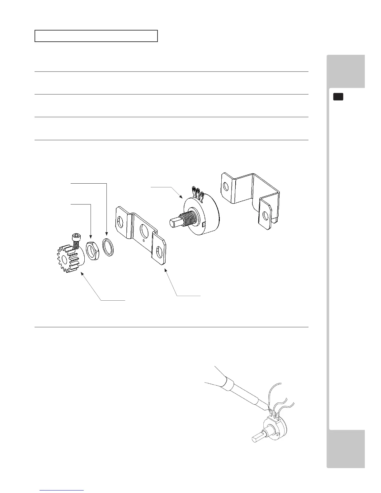
Slacken off the Gear retaining screw and pull the gear off the stem of the potentiometer.
3
Remove the nut securing the VR Bracket, then separate the Volume from the VR Bracket and replace it.
4
Remove the nut securing the VR Bracket, then separate the Volume from the VR Bracket and replace it.
5
Fit individual pieces of heat shrinkable tubing over the inulation of the (3) wires and solder them into place
in the same formation as when removed. When cool, place the tubing over each solder joint and heat to
shrink inplace.
Nut
Washer
VR Bracket
Pot