ASSEMBLY AND INSTALLATION
31
6
1
Information Display Screen
When “SYSTEM INFORMATION,” “STORAGE INFORMATION,” or “JVS TEST” has been selected on
the system test mode menu, system information, game information and information on JVS I/O board con-
nected to LINDBERGH are displayed.
If each category of information is displayed without anomalies, the LINDBERGH is normal.
2
JVS Input Test Screen
When “INPUT TEST” has been selected on the JVS test screen, data input to the JVS I/O board is dis-
played. On the product, this is the screen for the testing coin switch.
Insert a coin. If the display to the side of the switch changes, the switch and wiring connections are normal.
3
Monitor Test Screen
When “MONITOR TEST” has been selected on the system test mode menu, the screen for checking projec-
tor (monitor) adjustment status appears.
Projector adjustment is completed when the product is shipped from the factory, but you should observe the
test screen to determine whether further adjustment is necessary. Refer to Chapter 10 and adjust the projec-
tor if necessary.
4
Speaker Test Screen
When “SPEAKER TEST” has been selected on the system test mode menu, the screen for checking speaker
sound output appears.
To confirm that audio output is normal, have test sound output from the game unit’s speaker.
5
Input Test
When “INPUT TEST” has been selected on the game test mode menu, the screen for testing input device
appears. Test operate the input device by pressing each switch. If the display on the side of each input de-
vice changes to “ON” and numerical values change smoothly in accordance with each operation, the input
device and its wiring connections are normal. (See 9-3a.)
Use test mode to confirm that assembly is proper, and that the LINDBERGH, connecting boards, and input/output
devices are normal.
Perform the following tests in test mode.
For tests (1) to (4), refer to the LINDBERGH Service Manual. For tests (5) to (7), see [9-3 Game Test Mode].
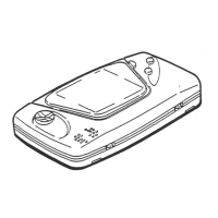
FIG. 6-14a INPUT TEST Screen
7 CONFIRMATION OF ASSEMBLY
INPUT TEST
PLAYER 1 2
TRIGGER OFF OFF
ACTION OFF OFF
CHANGE OFF OFF
GUN-X 000 000
GUN-Y 000 000
SCREEN OUT OUT
START OFF OFF
SERVICE OFF
TEST OFF
PRESS TEST AND SERVICE BUTTON TO EXIT