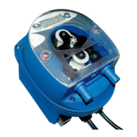
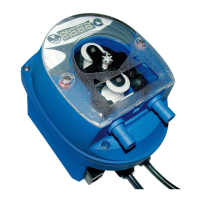
OPL BASIC cod. 0000136322
! Turn off the circuit breaker before installing or servicing the
Potentiometer for setting the
Potentiometer for setting the
Potentiometer for setting the
Adjustable from 0 seconds to 5 minutes
switch for pause time (LOCK
OUT). Lockout times can be set in 5 minute increments up to 75 minutes by
Input connector for level float switch:
Input connector for remote control:
The voltage to be applied may vary from 20 to 230
Jumper for selecting the power supply voltage of the device. The voltages that can be applied are 115
supply connector for device
CAUTION: The OPL BASIC has high voltage connected to the transformer. Always disconnect power
All electrical connections to the
system should first be verified with a meter. Application of
permanently damage the unit and is not covered under warranty. Avoid wiring to
any power source that has large fluctuations in voltage and/or is prone to surges. Refer to the wiring
diagram in this manual for all power and signal connections. All wiring mu
st conform to local electrical
To wire main power connection:
Check the voltage of the main power source and make sure that it matches one of the three available input
voltages (115/208/230 VAC) of the tran
Move the jumper to the proper terminals to set the input voltage (Picture 2) before connecting the power supply:
Disconnect all power from the laundry machine
Connect leads from the main power source to the Power terminals on the circuit board (