SELCO A/S M2500 Installation Manual
Revision: 23-04-2012 Page 23
5.4.2 Digital Outputs Out 1 to Out 12 (terminals 51 to 62)
Normally Open Relay output. These are programmable alarm and shutdown outputs. It is also
possible to program these outputs to activate with any of the alarms generated from the analogue
measurements.
Note:
In factory default configuration Digital Output 1 (terminal 51) is the START FAILURE OUTPUT.
In factory default configuration Digital Output 2 (terminal 52) is the STOP FAILURE OUTPUT.
5.4.3 REF 4 (terminal 50)
Common reference for all output relays terminals 51 to 62.
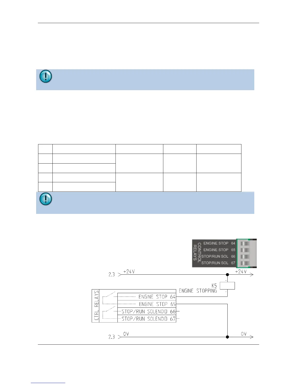
5.5 Control Relays
Energized to run or
energized to stop
Note: Cable break monitoring:
Cable break monitoring is required for the stop solenoid output. The nominal voltage for this output is
24V DC, 6A current when activated.
5.5.1 Engine Stop Output (terminal 64 and 65)
Terminals 64 and 65 are a normally open contact. This output will
be activated for the stop procedure until the stop time has expired
(energized to stop). The output is activated both for normal stops
and shutdowns. It is active in parallel with the stop solenoid relay.
Purpose of this output
is to give a potential
free signal to the
shut.
The relay is normally
de-energized