ASM 988A – Manual
16
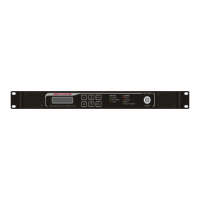
LED INDICATORS
There are seven LED indicators on the unit, three status indicators and four alarm
indicators. The three status indicators are to signal Power, Test and Local modes.
Status Indicators (3)
The Power indicator denotes that the unit is on.
The Test Mode indicator demarks whether the modulator is producing a modulated
output based on the input transport stream. When lit, the Test Mode indicator signals that
the unit is configured for use with an internally generated PN-23 input or to produce a
CW test signal.
The Local indicator denotes that the unit can only accept entries from the keypad, and
that all remote operations are disabled. During the time that the unit is being accessed
from the front panel, remote operations are disabled. This is a safety feature to prevent
the same parameter from being modified to different values during the same time.
Alarm Indicators (4)
The four alarm LED indicators demark different error conditions. These are the Input,
Output, Fault and Fault History alarms. These alarms are bi-colored. Green indicators
denote that the alarm has not tripped, while red indicators report failures.
The Input alarm indicates that the modulator is unable to lock to the input data stream or
that the incoming transport stream bitrate is different than what the Payload rate is set.
The Output alarm indicates that the modulator is unable to generate a correctly
modulated signal.
The Fault alarm indicates that a fault is present or did happen. The Fault alarm signals
that a voltage, temperature or fan is failing.
The Fault History alarm indicates that there are some events in the Fault log. When the
Fault History is disable, the Fault History alarm LED will be blank.