ASM 988A – Manual
2
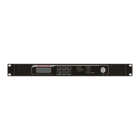
FRONT PANEL LAYOUT
1. Fan Intake with Removable Filter
2. Vacuum-Fluorescent Display (2 lines x 18 characters)
3. Keypad
4. Status LEDs
5. Alarm LEDs
6. Modulator Test Output –20 dB Attenuated Signal Strength (75Ω Terminated)
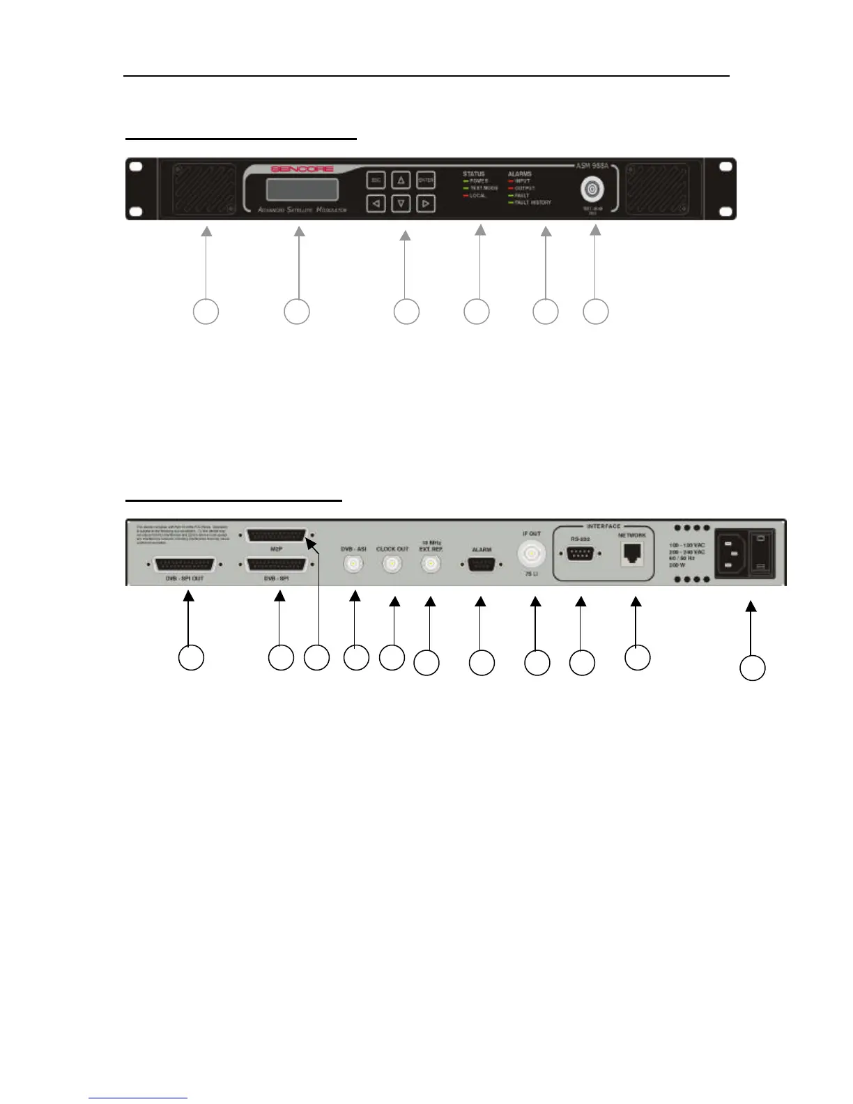
BACK PANEL LAYOUT
1. DVB-SPI Loopback Output. Available when ASI or M2P is used for input
2. DVB-SPI Input
3. M2P Input
4. DVB-ASI Input
5. Bit Clock Output. This can be used to control the rate of a multiplexer or an
encoder.
6. External 10 MHz Reference Input
7. Fault Alarm Output- Relay output
8. Modulator IF Output (75Ω Terminated)
9. Diagnostic RS232 Serial Port
10. Ethernet Port
11. 110/220 VAC Power Input and ON/OFF switch