SMP100 User Guide
7
3.2.2 Configuring Input
Embedded ASI Input
There a four built-in ASI interfaces on the back panel of the SMP100 chassis.
Steps to configure an ASI input:
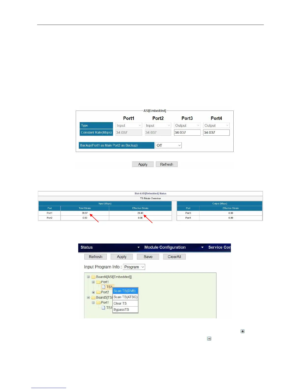
1. Go to Module Configuration > ASI [Embedded]. Enable an input channel or port. Since the
function of each ASI port is not editable, see the following image, you do not have to open or
close an ASI port. Port 1 and 2 are input ports. Port 3 and 4 are output ports.
2. Connect an ASI cable to ASI 1 IN interface.
3. Go to Status > ASI [Embedded] and verify the input bitrate of ASI port 1.
4. Go to Service Configuration. Right click the TS1 under Board4 [ASI] on the left of this page.
Click Scan TS (DVB) or Scan TS (ATSC) to search the input.
After a few seconds you will see a TS1 under Port 1, Board4. You click the plus icon ( ) in
front of TS1 to see the detailed list of all services. Click the minus icon ( ) to hide the details.