VP400 Series Video Pro Form7343A Operation Manual
37
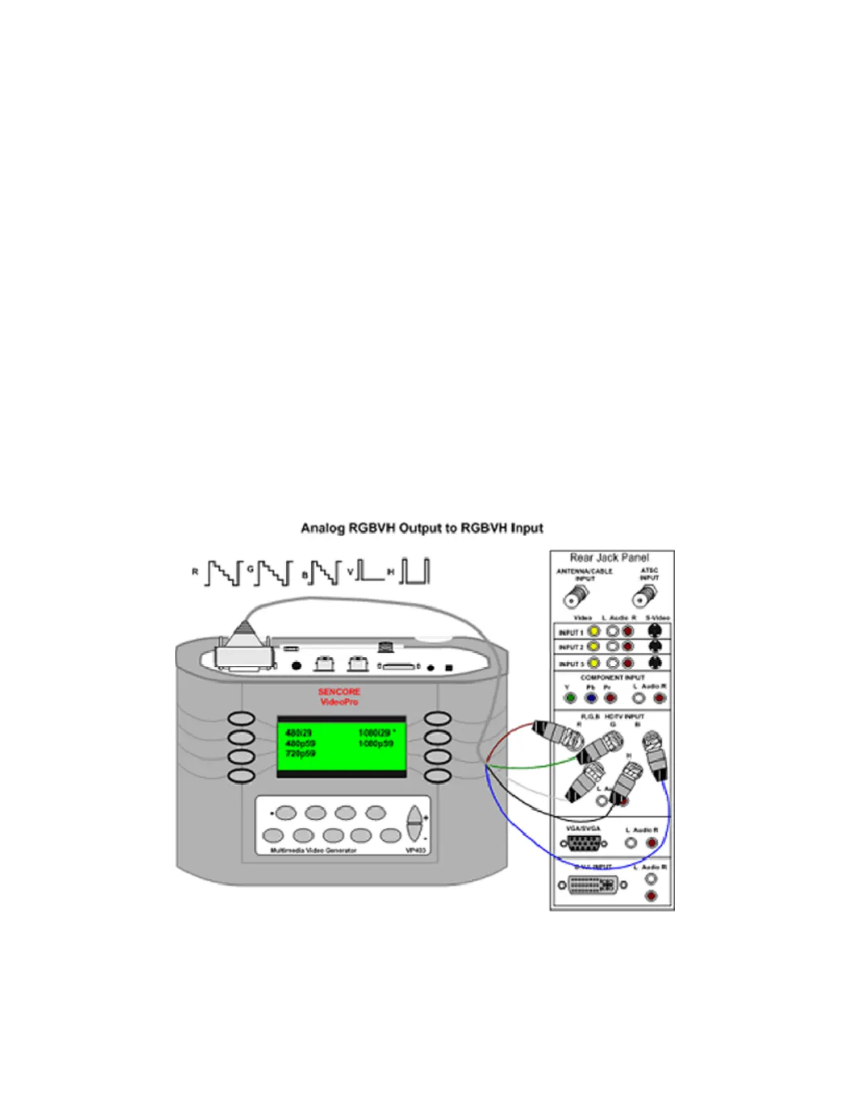
RGB to RGB HDTV Input
An HDTV/SDTV video signal may be interfaced between a receiver/decoder and a display using
an RGB signal. This interface may use all 5 wires (R,G,B,H,V), 4 wires (R,G,B, Composite
Sync) or 3 wires (R,G & composite Sync, B). The number of BNC connectors on the display
input indicates the variation that is being used.
The VideoPro can be used to supply any of
these RGB signal input variations. In the
Gating menu, select DSS when a 5 wire
system is used. This is the default setting
when using the VideoPro. Select DCS when a
4 wire RGB system with composite sync is
being used. Select ACS when analog sync is
being added to the green signal wire in a 3
wire RGB interface.
To supply an HDTV signal from the
VideoPro to the RGB display inputs, connect
the DVI to BNC connector cable (39G1059)
from the generator’s DVI Output to the RGB
inputs of the display. The red, green and blue
colored cables are the R, G, B signals
respectively. The black cable is the horizontal
signal (DSS) or the composite sync (DCS).
To output the proper signal from the
VideoPro, select the HDTV/SDTV- RGB
signal type from the Signal Type menu. Select
the resolution format (Ex 1080i29) from the
Format menu. Select the HDTV-RGB input
on the display/monitor’s input menu screen.
The video pattern from the generator should
be visible on the display screen.
 Loading...