VP400 Series Video Pro Form7343A Operation Manual
41
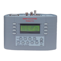
Display Data Channel (DDC)
Display Data Channel (DDC) is a
communications channel between a
signal source and a display. DDC
was originally developed to enable
a computer to learn what resolution
formats a display that was
connected to its video output was
capable of displaying. This was in
support of Plug & Play protocols
developed through the Video
Electronic Standard Association
(VESA). Once the computer
learned what formats the monitor
could display, it automatically
selected the highest resolution
format for optimum performance.
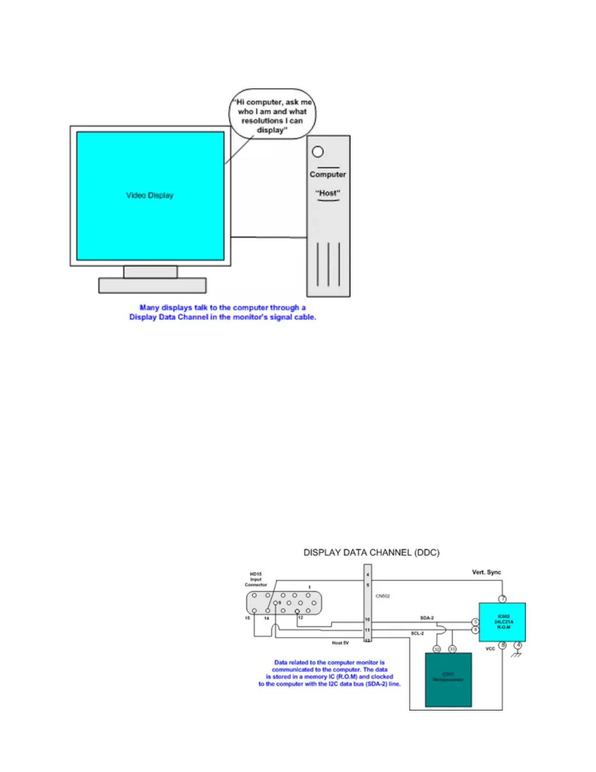
DDC was originally specified for
use with standard VGA 15 pin HD
connectors. Since its definition, all newer connection plugs, including DVI and EVC, have
specified pins for DDC compatibility. DDC is no longer confined to computers and computer
monitors as other display devices and signal sources are integrating DDC capabilities.
DDC uses an I2C communications bus
between the computer or host device. This
bus uses two lines including a serial clock
(SCL) line and a serial data (SDA) line.
Communication over these lines can be either
uni-directional or bi-directional. Several
revisions of DDC protocols have evolved.
DDC1 is uni-directional from the display to
the host, display data is sent continuously,
clocked by vertical sync. DDC2B, DDC2B+
and DDC2AB are bi-directional, with the host
initiating a request for data and
the display then transferring the
data. DDC2B involves a simple
command by the host followed by
reading data (EDID information)
from the I2C slave memory IC.
DDC2B is used by the VideoPro
400 series generators.
Extended Display Identification
Data (EDID) defines the data and
orientation of the data over the
DDC channel. The data can
include manufacturing and model
information, but more importantly, resolution
information regarding the compatible formats
that display can properly display. When the
EDID data is decoded, a host device can
determine which of the standard VESA
formats, along with other formats, are
compatible with the display. The VideoPro
400 series reads the EDID data and lists the
formats that can be produced by the
generator. These formats can be selected and
output to the display in the DDC Step sub-
 Loading...