VP400 Series Video Pro Form7343A Operation Manual
39
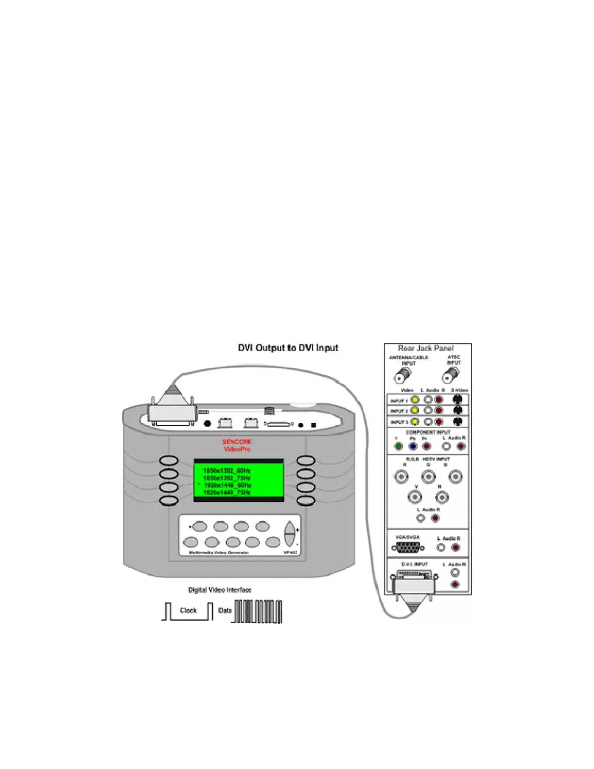
DVI to DVI Input
A digital signal interface is available to move signals from a source to a display. The video signal
is digitized into several data streams and clocked to the display. The display’s circuitry decodes
the input data to produce the original video. A DVI signal generator produces the DVI data and
clock signals comprised of video test patterns for testing the DVI inputs.
To test the DVI inputs of a display, connect
the DVI test lead (39G1060) between the
generator and the DVI inputs of the monitor.
Select either the HDTV/SDTV –DVI or
VESA/Mac – DVI selections in the Signal
Type menu. Use the HDTV/SDTV–DVI
when testing HDTV/SDTV monitors. Use the
VESA/Mac – DVI signal type when testing
computer monitors, data projectors and multi-
media projectors.
Note: Many multi-media displays are capable
of receiving and decoding both HDTV/SDTV
and VESA/Mac signal formats.
Select a signal format from the Format menu
that provides a signal resolution within the
range of the display. Select the DVI Input
from the monitor’s input menu. The monitor
should decode the DVI signal and display the
video test pattern.
 Loading...