ENGLISH
Pag. 13
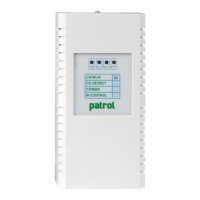
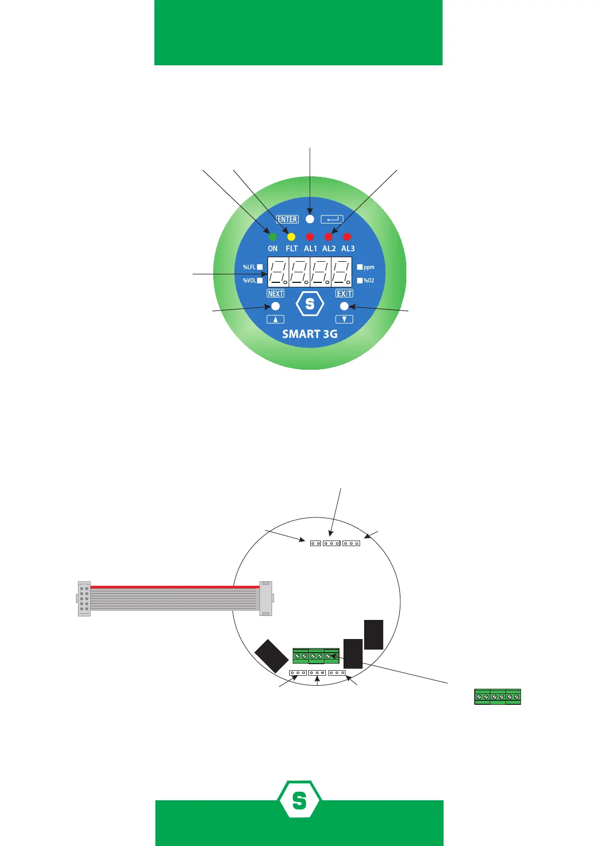
2.1 Board layout
Power ON LED Fault LED Alarm 1, 2 and 3 LEDs
4 digits display
NEXT magnet EXIT magnet
JP7
JP9
JP12
RELAY 1
RELAY 2
RELAY 3
1 1 1
1 1
JP8 JP13 JP10
JP4
JP7 on SMART3G base board
Connection to the gas detector
JP8
Open: relays normally energized
Chiuso: relays normally not energized
PIN 1-2 closed: Alarm 1 relay 2
JP10
PIN 2-3 closed: Alarm 2 relay 2
PIN 1-2 closed: Alarm 2 relay 3
PIN 2-3 closed: Alarm 3 relay 3
Relay 2 and 3
associated to alarms
Relay 1 always
fault associated
JP7, JP9 and JP12 set relays status
JP7 PIN 1-2 closed: Relè 1 normally closed
JP12 PIN 1-2 closed: Relè 3 normally closed
JP9 PIN 1-2 closed: Relè 2 normally closed
Jp12 PIN 2-3 closed: Relè 3 normally open
JP7 PIN 2-3 closedi: Relè 1 normally open
JP9 PIN 2-3 closed: Relè 2 normally open
JP6 relays output connections
COM1
NO1/NC1
NO3/NC3
COM2
COM3
NO2/NC2
JP6
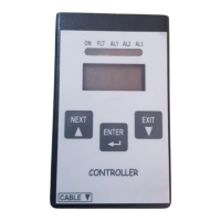
Figure 2) Front view of SMART3G display
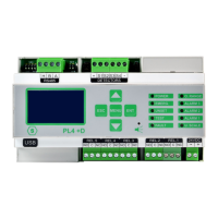
Figure 3) Inside view of SMART3G display