ITALIANO
Pag. 3
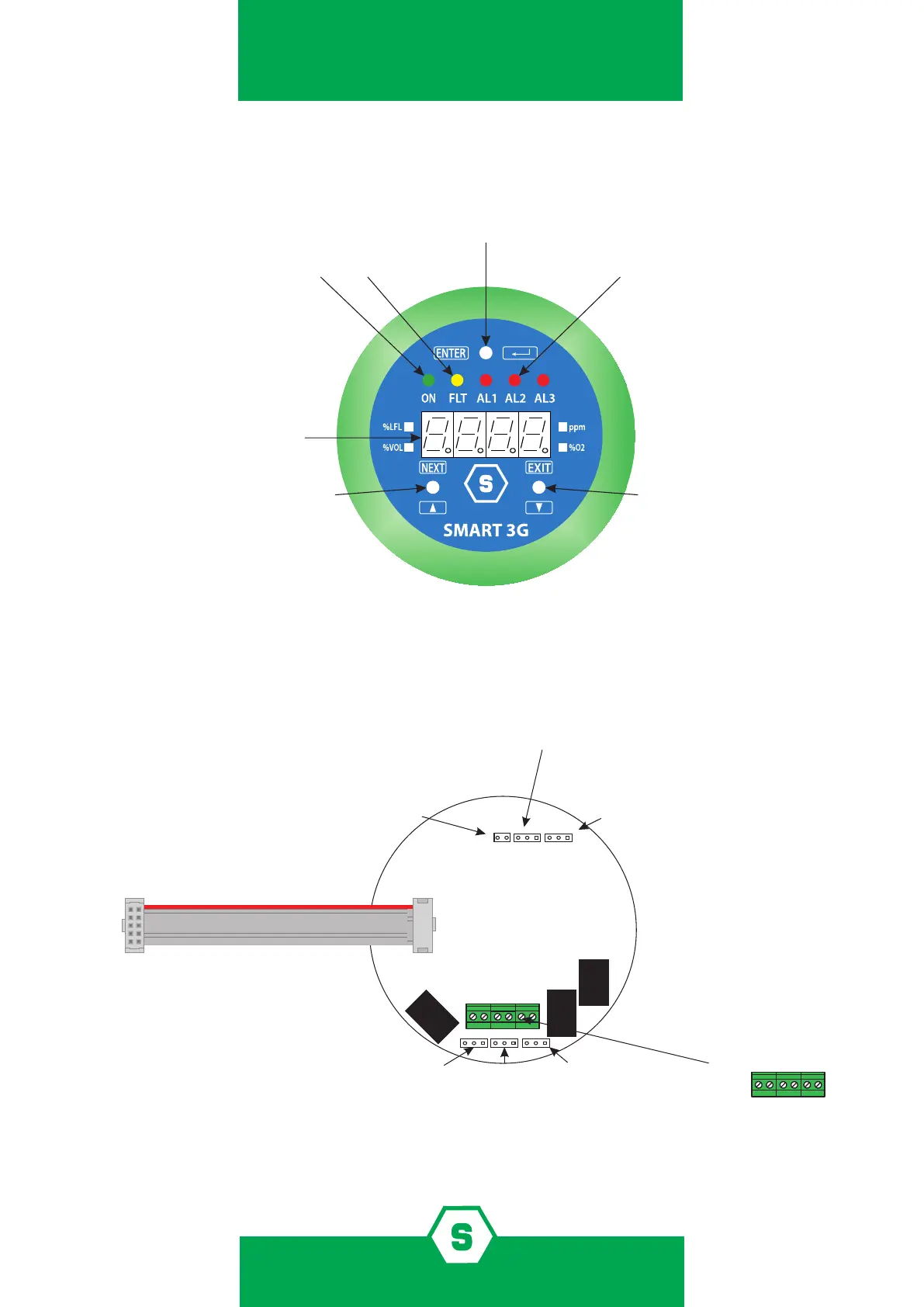
Schema topograco
LED accensione LED di fault LED allarmi 1, 2 e 3
Display 7 segmenti
Magnete NEXT Magnete EXIT
JP7
JP9
JP12
RELÈ 1
RELÈ 2
RELÈ 3
1 1 1
1 1
JP8 JP13 JP10
JP4
JP7 sulla base SMART3G
Connessione al rilevatore
Aperto: relè normalmente energizzati
Chiuso: relè normalmente non energizzati
JP8
PIN 2-3 chiusi: Allarme 2 su relè 2
JP10
PIN 1-2 chiusi: Allarme 1 su relè 2
PIN 2-3 chiusi: Allarme 3 su relè 3
PIN 1-2 chiusi: Allarme 2 su relè 3
Relè 2 e 3 associati
alle soglie di allarme
Relè 1 sempre
associato al fault
JP7, JP9 e JP12 impostano lo stato dei relè
JP7 PIN 1-2 chiusi: Relè 1 normalmente chiuso
JP7 PIN 2-3 chiusi: Relè 1 normalmente aperto
JP9 PIN 1-2 chiusi: Relè 2 normalmente chiuso
JP9 PIN 2-3 chiusi: Relè 2 normalmente aperto
Jp12 PIN 2-3 chiusi: Relè 3 normalmente aperto
JP12 PIN 1-2 chiusi: Relè 3 normalmente chiuso
JP6
JP6 connessione uscite relè
COM1
NA1/NC1
COM2
NA2/NC2
NA3/NC3
COM3
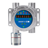
Figura 2) Lato frontale del display
Figura 3) Lato interno del display