SG-2000 MANUAL 26
The SGC Building, 13737 S.E. 26th St. Bellevue, WA. 98005 USA
©1995, SGC, Inc. TEL: (206) 746-6310 FAX: (206) 746-6384
From left to right, these jacks provide the following:
J-502 SG-230/SG-235 Smartuner™ connections
J-301 Aux. Audio input/output and PTT line
J-503 Remote control head or multiple head junction box
J-504 Remote control head or multiple head junction box (Head mounted on radio is
normally connected here.
Ext Spk External Speaker (or Weatherfax modem)
Oven Turns oven On-Off (Shipped with oven ON as default)
Pin outs of the external coupler jack and the Audio Input/Output jack are listed below.
These may also be found in the SG-2000 Technical Reference in appropriate schematics.
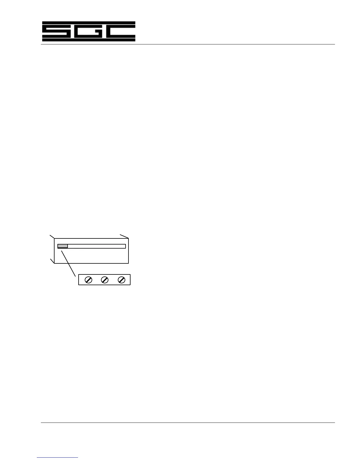
9.2 External Coupler Installation
Connector J-502 is used to connect the SG-2000 to an external coupler. Details are
shown in the diagram below:
J-502 Pin 1: Coupler Ground. (Black wire from SG-230/SG-235)
Pin 2: Coupler +12 VDC. (Red wire from SG-230/SG-235)
Pin 3: Remote Tuned Indicator (Black/White wire from
SG-230/SG-235)
Do not connect the Red/White wire from the SG-230/SG-235 as
this wire is used to control coupler functions. See SG-230/SG-235
manuals for details on coupler control options via this wire.
1 2 3
Coupler Connections on rear
panel of SG-2000