Do you have a question about the SGC SG-2000 and is the answer not in the manual?
Provides a detailed overview of the SG-2000 transceiver's core features and specifications.
Outlines the necessary voltage and current specifications for operating the SG-2000.
Details the technical performance metrics of the SG-2000 receiver and transmitter.
Describes the SG-2000's compatibility and specifications for data communication modes.
Explains how the SG-2000 can be controlled remotely via a computer interface.
Details the capabilities and specifications for using multiple control heads with the SG-2000.
Provides the physical dimensions and weight of the SG-2000 unit for installation planning.
Lists the key standard features and functionalities offered by the SG-2000 transceiver.
Lists optional external accessories that can be connected to the SG-2000.
Lists optional internal accessories or configurations available for the SG-2000.
Details the internal signal flow and processing within the SG-2000 receiver section.
Describes the signal processing and amplification stages within the SG-2000 transmitter.
Explains the microprocessor-based control system and communication protocols used in the SG-2000.
Discusses the design considerations and advantages of the SG-2000's control head architecture.
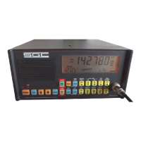
Describes the features and design of the SG-2000's front control panel and its ruggedness.
Details the connectors and ports available on the rear panel of the SG-2000 unit.
Describes the four models of remote mobile heads designed for the SG-2000.
Introduces the PowerTalk™ control head and its noise reduction capabilities.
Details a special edition of SG-2000 software adapted for differential GPS radio location service.
Describes special software that allows emergency distress tone transmission on all frequencies.
Offers advice on selecting appropriate locations for power supplies to ensure optimal performance.
Discusses flexible placement options for SG-2000 control heads in marine and mobile environments.
Provides guidance on wiring control heads, emphasizing precautions for high vibration environments.
Explains how to connect external speakers and headphones to the SG-2000.
Advises on planning for the installation of various external accessories.
Details the types of station licenses issued by the FCC and their applicability to the SG-2000.
Outlines the operator license requirements and types necessary for using the SG-2000.
Illustrates and describes the rear panel connections for peripherals and accessories of the SG-2000.
Details the procedure for installing an external antenna coupler, including connector pinouts.
Explains connections for external modems, Weatherfax, and High Seas Direct™ systems.
Discusses duty cycle considerations and the importance of heavy-duty cooling options for continuous operation.
Provides step-by-step instructions for mounting the SG-2000 in a standard 19" equipment rack.
Describes methods for installing remote control heads for the SG-2000.
Details the installation procedure for the remote head kit, extending the control head's reach.
Explains how to add multiple control heads using a junction box for the SG-2000.
Provides instructions on how to extend the length of the control head cable for remote installations.
Offers guidance on designing power cabling to minimize voltage drop and ensure reliable performance.
Compares conventional transformer-rectifier supplies with switching type supplies for the SG-2000.
Highlights the reliability and advantages of transformer-rectifier power supplies.
Covers power sources for mobile installations, including vehicle alternators and batteries.
Discusses design considerations for solar charging systems to power the SG-2000.
Details the impact of antenna wire size on radiation efficiency and effective radiated power.
Describes the NVIS technique for short-distance HF communication and its antenna requirements.
Discusses antenna types suitable for fixed stations based on communication distance requirements.
Explains the importance of transmission lines and the advantages of 50-ohm coaxial cable.
Details the function and benefits of antenna couplers for matching antennas to the SG-2000.
Discusses various mobile antenna types, their history, and selection criteria.
Recommends the SGC QMS antenna system for mobile HF installations, detailing gain advantages.
Briefly touches upon alternative mobile antenna configurations like "J" and loop antennas.
Explains the SG-2000's memory and channel architecture, differentiating it from other radios.
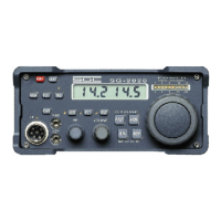
Describes the layout and components of the SG-2000 control head's front panel.
Details the basic and frequency functions of the SG-2000's push buttons.
Provides practical examples of key entry sequences for common operating tasks.
Explains the meaning and function of the various indicators and displays on the SG-2000's front panel.
Details the primary functions of the buttons located on the SG-2000's front panel.
Describes the fundamental functions of the SG-2000's keyboard buttons, including SHIFT/FUNC and PRGM.
Explains how to access and use the secondary functions of the SG-2000's keys.
Outlines the various functions available for programming channels, timers, frequencies, and scan banks.
Guides users through practical key entry sequences for operating the SG-2000.
Explains how to change channels in both voice and telex modes, including SITOR channels.
Details methods for changing the operating frequency of the SG-2000, including direct entry and incremental tuning.
Covers procedures for programming user channels into memory and handling duplex channels.
Explains how to perform frequency, channel, and scan bank scanning operations on the SG-2000.
Describes how to adjust scan rates for both frequency and channel scanning modes.
Covers additional functions like timer settings, display toggling, and beep options.
Discusses the importance of shock mounting and how to estimate its necessity based on vibration factors.
Offers guidelines for establishing effective ground systems in mobile installations to minimize noise and ensure efficiency.
Identifies common sources of vehicular noise that can affect radio performance and provides solutions.
Provides recommendations for mounting the SG-2000 radio unit and control head in marine installations.
Details the process of establishing proper "bonding" and ground systems for marine HF radio installations.
Discusses antenna types and placement recommendations for sailboats and motorboats.
Provides information on connecting the AT&T High Seas Direct system to the SG-2000.
Details how to extend the control head wiring to achieve remote operation of the SG-2000.
Describes using telephone lines and short haul modems for remote SG-2000 control.
Clarifies the responsibilities between SGC and users regarding system integration beyond the radio.
Discusses the use of auto-answer systems for telephone-based remote control of the SG-2000.
Explains how to control the SG-2000 via computer networks using serial connections.
Details the Softlink RS-232 software for comprehensive computer control of the SG-2000.
Provides system requirements and step-by-step instructions for installing the RS-232 control software.
Explains the layout and parameters displayed in the main menu of the RS-232 control software.
Describes the operations accessible from the main menu of the RS-232 control software.
Details the functions available within the second menu of the RS-232 control software.
Explains how to use the RS-232 software to program various functions like scan banks and timers.
Shows how to construct PC serial cables for connecting the SG-2000 to computers with different RS-232 connectors.
Explains how the SG-2000 operates with ALE controllers via its serial port.
Details the serial communication protocol and parameters used between the SG-2000 and ALE controllers.
Provides examples of commands used for controlling the SG-2000 via an ALE controller.
Explains how to recall stored memory settings for active use with ALE control.
Lists the physical connections required between the SG-2000 and an ALE controller.
Describes the EXSEL-100 unit for digital selective calling, compatible with SSB transceivers.
Details the TELEREX-ST error-correcting data terminal for text communications.
Provides troubleshooting advice for common operational issues and malfunctions encountered with the SG-2000.
Explains a specific scanning behavior and how to correct it by managing programmed scan frequency provisions.
Details the procedure for recalibrating the squelch level on the SG-2000 transceiver.
Provides instructions for resetting the SG-2000's microprocessor, with warnings for inexperienced operators.
Explains how to activate the emergency beacon and alarm functions on the SG-2000.
Offers a step-by-step guide for basic alignment and tune-up procedures for the SG-2000.
Describes how to bypass the AM filter to enable reception in the AM band down to 500 KHz.
Lists and describes the major modules and their functions within the SG-2000's oscillator and filter system.
Details the components and responsibilities of the SG-2000's microprocessor assembly.
Explains the function of Voltage Controlled Oscillators (VCOs) in generating frequencies for modulation.
Describes how Phase Lock Loop (PLL) circuits work with VCOs to produce required voltages.
Explains the function of serial logic switches in controlling relays and power settings.
Describes the tone generator's role in producing audio tones based on reference clock signals.
Details the function of the oven switch for selecting continuous or switched power supply to the oven unit.
Explains how the alarm generator is activated for emergency use, producing specific tones.
Describes the self-contained 11.94 MHz master oscillator with an oven for frequency stability.
Explains the solid-state regulated oven that maintains the 11.94 MHz reference oscillator's temperature.
Lists the upper cut-off frequencies of six low pass filters used to eliminate harmonic distortion.
Details the Automatic Level Control (ALC) circuit's function in maintaining output power levels.
Describes how modulation characteristics and audio frequency response were tested and plotted.
Explains the procedure for testing modulation characteristics and peak envelope power limiting.
Outlines the setup for testing SG-2000 transceiver performance using specific equipment.
Lists common malfunctions and their probable causes, offering initial troubleshooting steps.
Explains a specific scanning behavior and how to correct it by managing programmed scan frequency provisions.
Outlines the required equipment and procedures for testing the SG-2000's exciter subassembly.
Lists the necessary instruments and equipment for performing exciter testing.
Describes the circuit components and functions of the Voltage Controlled Oscillator (VCO) sections.
Details the procedure for testing the 11.94 MHz reference oscillator, including voltage and frequency checks.
Provides steps for checking the functionality of various VCOs (4, 10.7 MHz and 72-76 MHz).
Explains how to perform a receive sensitivity check, including calibration of the 82 MHz filter.
Describes a test to show the relationship between the 82 MHz IF filter and displayed frequencies.
Provides detailed procedures for aligning the SG-2000 in SSB modes, including critical adjustments.
Outlines the steps for aligning the SG-2000 in AM modes after successful SSB alignment.
Details the procedure for checking the function and attenuation levels of the 20 dB attenuator.
Explains how to adjust the Automatic Gain Control (AGC) for optimal audio output levels.
Describes how to check the audio output levels at the 600 ? port (J301).
Details the procedure for checking the audio output levels at the head port (J503/J504).
Explains how to check the performance of the voice and telex audio filters.
Provides steps for calibrating the transmitter output power and ensuring proper RF drive to the LPA.
Details how to adjust microphone gain for optimal audio input levels during transmission.
Explains how to adjust the CW tone level for proper transmission.
Outlines the procedure for checking the 600 ? port levels during transmit.
Provides steps for aligning the SG-2000's SSB transmit stages for optimal performance.
Details the process for adjusting carrier insertion levels for A3A and A3H transmission modes.
Explains how to adjust the 30 MHz low-pass filter for optimal RF output.
Describes how to check and adjust the Automatic Level Control (ALC) system.
Details how to check the coupler port for proper receive tuning status indication.
Explains how to verify the functionality of the alarm generator for emergency transmissions.
Describes how to test the SG-2000's ability to recover after a power interruption.
Provides troubleshooting steps for common issues encountered during receive operations.
Guides users through troubleshooting steps for VCO failures, including PLL checks.
Lists the necessary equipment for testing the LPA PCB of the SG-2000.
Provides a circuit description of the LPA, detailing its amplifier stages and filter sections.
Outlines the test setup and initial checks for the LPA sample board.
Details tests for the voltage protection circuit, specifically for Rev E boards and later.
Describes how to test the upper edge of low pass filters using a tracking generator and spectrum analyzer.
Provides detailed steps for aligning the SG-2000's transmit stages, including voltage checks.
Explains how to check and adjust the Automatic Level Control (ALC) system.
Details the procedure for checking the temperature sensor's functionality and trigger points.
Lists the necessary equipment for testing the SG-2000's display section.
Explains the circuit components and functions of the SG-2000 display board.
Outlines the test setup and initial checks for the display section.
Details the procedure for testing the LCD display using a special program.
Describes how to test the receive audio path, including connections and settings.
Explains how to perform an S-meter test using an audio generator and distortion analyzer.
Details the procedure for checking the speaker output levels and clipping.
Explains how to check the audio levels for the phone connection.
Describes how to test the squelch function to ensure proper operation.
Details the process of checking speaker clipping levels with an oscilloscope.
Covers transmit tests related to the microphone, including level checks for dynamic and carbon types.
Details the procedure for checking the level of dynamic microphones, with and without a voice compressor.
Explains how to check the level of carbon microphones.
Describes how to check transmission quality using carbon and dynamic microphones.
Advises to check that all button functions operate properly and display the proper readouts.
Lists the necessary equipment for testing the CPU subassemblies.
Provides a circuit description for the Head Processor and Main Processor boards.
Details the pre-testing steps and visual inspections for the CPU boards.
Describes a test procedure for verifying the functionality of the microprocessor ports.
Details the procedure for testing the real-time clock functionality.
Explains how to test data signals for TXD and RXD on the UART.
Provides instructions for installing the battery on the Main CPU board.
Outlines operational tests to verify proper function after CPU installation.
Presents truth tables for reference logic ICs used in the SG-2000.
Lists the initial tests performed on the SG-2000 before undergoing 12 hours of continuous transmission testing.
Describes the tests conducted after the initial 12-hour rack test and before the second 12-hour cycle.
Lists the final inspections performed before the SG-2000 unit is shipped to the customer.
| Brand | SGC |
|---|---|
| Model | SG-2000 |
| Category | Transceiver |
| Language | English |