38
27DV-S100
27DV-CS10
3 Next, change the alignment top to VROEFZCS to
play back. Press the tracking button (+), (–) and
change the envelope waveform from max to min
and from min to max. At this time adjust the height
of supply and take-up side guide roller with the
adjustment driver (JiGDRiVERH-4) so that the en-
velope waveform changes nearly parallel.
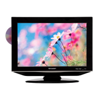
4 If the tape is lifted or sunk from the helical lead
surface, the PB CHROMA envelope waveform ap-
pears as shown in Figure 1-35.
5 Press the tracking button (+), (–) and make sure
that the envelope waveform changes nearly paral-
lel.
6 Finally check tape crease near the reverse guide. If
tape crease is found, remove it as stated in page 36
"HEIGHT ADJUSTMENT OF REVERSE GUIDE"
item 3.
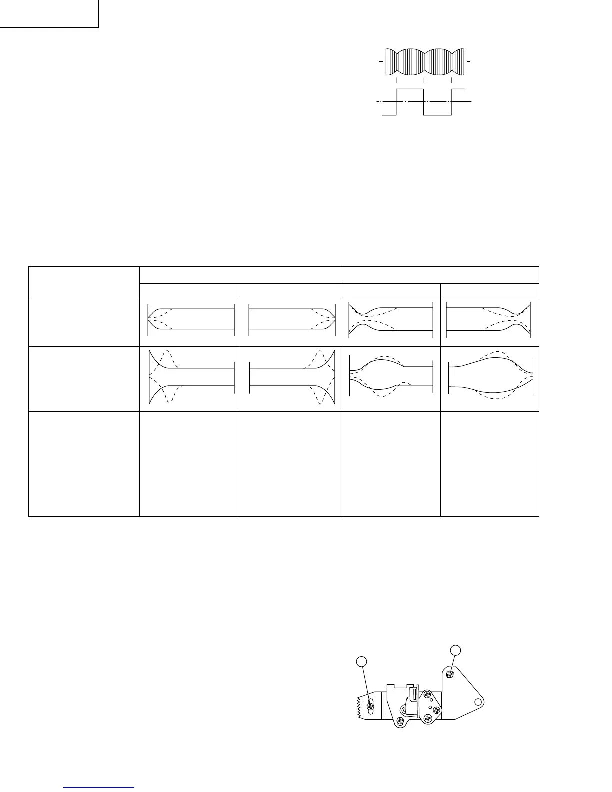
4. A/C head X value adjustment
1 Tentatively fix A/C head arm screws 1 and 2 by the
method described in page 35 "Replacement 3".
2 After shortcircuiting R7057 and JUMPER:420, plug
in the powercord, then turn off the power. And set
the alignment tape (VROEFZCS) into the unit, turn
on the power, then playback it. As a result the auto-
tracking is automatically cancelled, so that the X
value adjustment mode is set.
Take-up side Supply side Take-up side
Adjustment
Supply side
Supply side guide roller
rotated in clockwise
direction (lowers guide
roller) to flatten
envelope.
Take-up side guide roller
rotated in clockwise
direction (lowers guide
roller) to flatten
envelope.
Supply side guide roller
rotated in counterclock-
wise direction (raises
guide roller) to make the
tape float above the helical
lead. The supply
side guide roller is then
rotated in the clockwise
direction to flatten the
envelope.
Take-up side guide roller
rotated in counterclock-
wise direction (raises
guide roller) to make the
tape float above the
helical lead. The take-up
side guide roller is then
rotated in the clockwise
direction to flatten the
envelope.
When the tape is below the helical lead.When the tape is above the helical lead.
3 Move the A/C head with the X value adjustment
gear driver by the method shown in Figure 1-33,
and adjust the A/C head so as to get the maximum
envelope waveform. (Note: At this time adjust so as
to get the maximum envelope waveform nearest
the A/C head position which has been set in case of
X value rough adjustment as stated in page 37, 3-
2.)
4 Tighten finally the screws 1 and 2. Be sure to
tighten at first the screw 1 and then the screw 2.
Final tightening torque is 0.6N·m (If the screw 2 is
tightened first, the X value may deviate.)
5 Adjust the playback switching point (Refer to the
electric adjustment method.)
6 Playback the self-picture-recorded tape, and check
the flatness of envelope waveform and sound.
• Problems caused by maladjustments
1. Totally maladjusted
• Tapes may get scratched.
• Images onscreen may get distorted or affected by
noises, or may fail to appear.
• The linear audio level may get degraded.
Note:
When the A/C head X value adjustment is performed, be
sure to perform at first X value rough adjustment (refer to
page 37, 3-2).
Figure 1-35.
Figure 1-36.
1
2
Figure 1-34.
CH-1 CH-2
Head switching pulse
PB CHROMA
Envelope