4. Fusing section
A. List
No. Part name Ref. page
1 Thermistor 8-5
2 PPD2 sensor 8-5
3 Heater lamp 8-6
4 Pressure roller 8-5
5 Heat roller 8-5
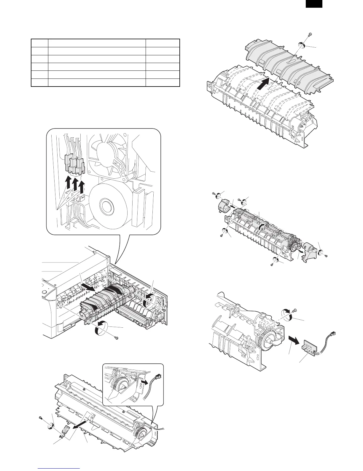
B. Disassembly procedure
(1) Remove the connectors (3 pcs.) of the rear cabinet.
(2) Open the side cover, remove two screws, and remove the
fusing unit.
(3) Cut the binding band, remove the screw, and remove the
thermistor.
(4) Remove the screw and remove the U-turn guide.
Pressure roller section disassembly
(5) Remove the three screws, remove the fusing cover lower
on the right side, and open the heat roller section.
(6) Remove the screw and remove the PPD2 sensor.
1)
2)
3)
Thermistor
1)
2)
3)
2)
1)
2)
1)
5)
5)
6)
6)
4)
3)
2)
1)
2)
PPD2 sensor
AL-1000/1010
8-5