(6) Remove the C-ring and the fusing bearing, and remove the
heat roller.
(7) Remove the parts from the heat roller.
Note: Apply grease to the sections specified with ✽.
(8) Remove two screws and remove the thermo unit.
C. Assembly procedure
For assembly, reverse the disassembly procedure.
5. Tray paper feed/transport section
A. List
No. Part name Ref. page
1 PPD1 sensor PWB 8-11
2 LSU unit 8-10
3 Intermediate frame unit 8-10
4 Paper feed roller 8-11
B. Disassembly procedure
(1) Remove six connectors and screws of the main PWB, and
lift the optical unit and the main PWB to remove.
(2) Remove the PWB insulation mylar and remove the paper
transport detection sensor (PPD2).
1)
2)
3)
Heat roller
1)
2)
3)
✽
✽
1)
2)
3)
2)
3)
2)
2)
2)
1)
1)
1)
3)
2)
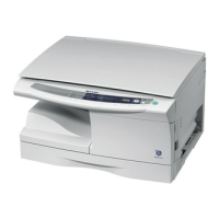
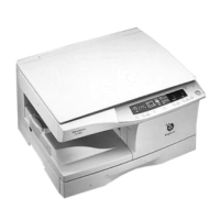
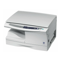
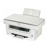
AL-1000/1010
8-7