(2) ASIC
1. Outline
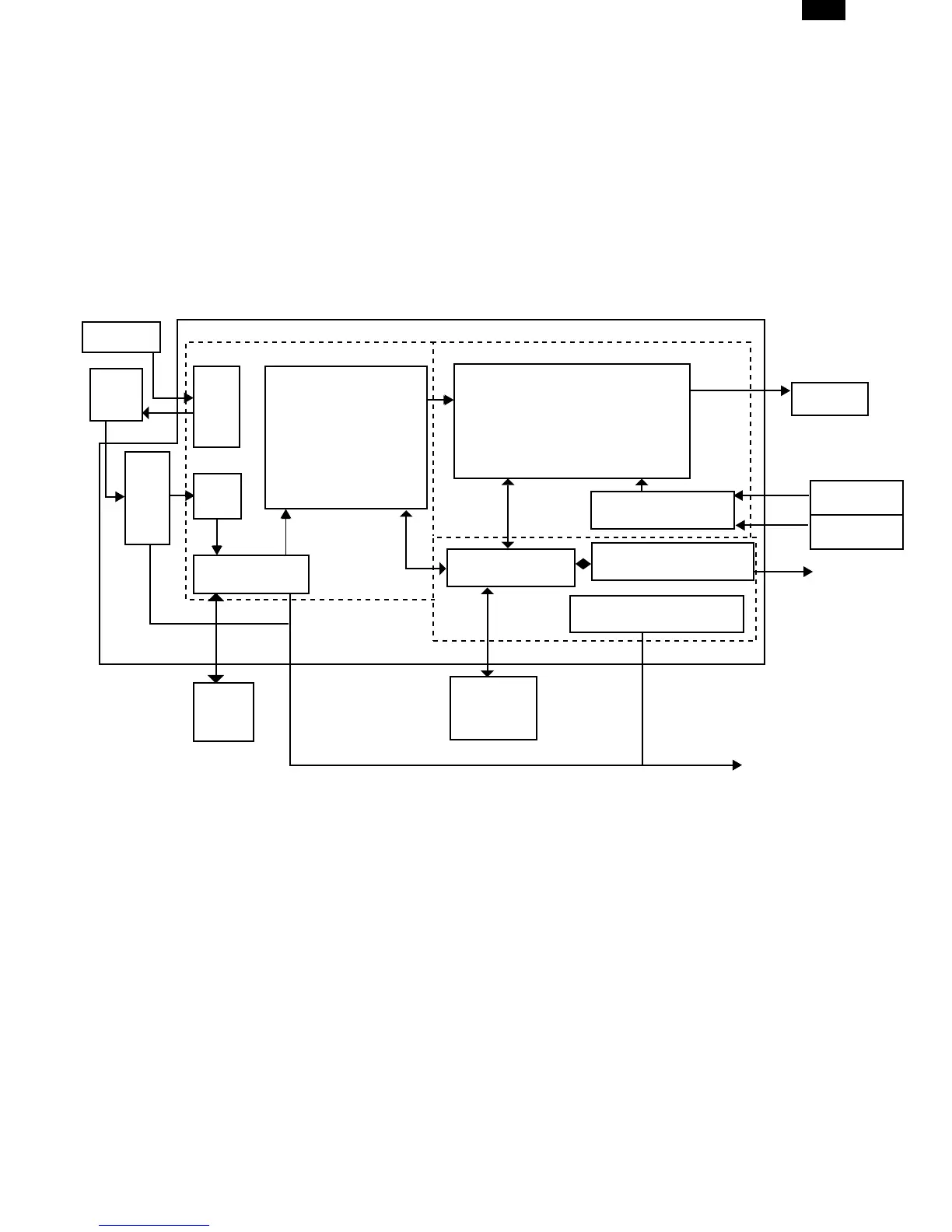
Fig. 4 shows the block diagram of the ASIC.
The ASIC is composed of the following three blocks; the image process section, the print control section, and the I/F section.
The image process section processes the image data from the CCD PWB according to the operation mode, such as shading, AE
process, resolution conversion. and zooming.
The print control section outputs the image-processed data during copying to the LSU (Laser unit) in synchronization with writing
timing of the LSU.
The I/F section controls communication of interface (IEEE1284) with the host PC and controls DRAM of send/receive data buffer with
the host PC. (Only for models with the printer function)
The ASIC is controlled by the CPU which writes the operation mode and the set values necessary for each operation mode to the
ASIC control register.
Scan start
CCD
PWB
Shading
CCD drive
AE
SRAM control
SRAM
32KB
x 2
Resolution conversion,
Zooming, lmage
process circuit
Print data process circuit
DRAM control
PRINT control
IEEE1284 control
DRAM
6MB or 4MB
LSU
HSYNC
VSYNC
To CPU bus
TO PCI/F
PWB
ASIC
Image process section
I/F section
Print control section
ASIC control resistor
(Only for models
withthe printer
function)
AL-1000/1010
12-6