– 13 –
CD-BA3100
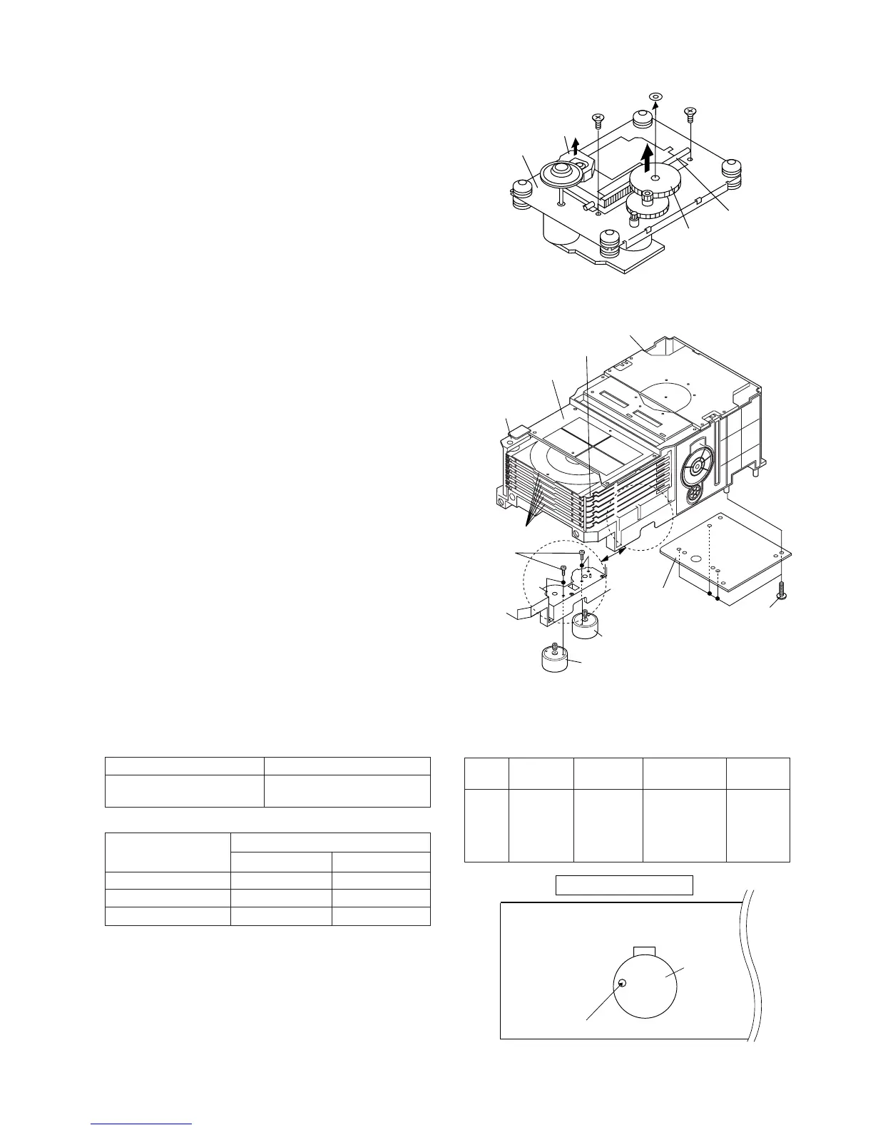
Figure 13-2
Figure 13-1
ADJUSTMENT
MECHANISM SECTION
• Driving Force Check
Torque Meter Specified Value
Play: TW-2111 Tape 1: Over 80 g
Tape 2: Over 80 g
• Torque Check
Torque Meter
Tape 2
Play: TW-2111 30 to 80 g.cm 30 to 80 g.cm
Fast forward: TW-2231 — 70 to 180 g.cm
Rewind: TW-2231 — 70 to 180 g.cm
Specified Value
Tape 1
Specified
Value
Adjusting
Point
Instrument
Connection
Test Tape
Normal MTT-111 Variable 3,000 ± 30 Hz Speaker
speed Resistor in Terminal
motor. (Load
resistance:
6 ohms)
• Tape Speed
Figure 13-3
TAPE MECHANISM
Tape
Motor
Variable Resistor in motor
(A1) x1
ø2.6 x6mm
CD
Mechanism
Stop Washer
(A3) x1
Gear
(A4) x1
Shaft
(A2) x1
Pickup
(A1) x1
ø2.6 x6mm
Main Cam Motor
Tray Motor
CD Servo
PWB
(1)Front Top Plate
(2)Changer Box,
Left
(2)Changer Box,
Right
(3)Disc Tray,1~6
CD Changer Mechanism
(B1)x4
ø3x10mm
(B2)x4
ø2.6x4mm
CD MECHANISM SECTION
Perform steps 1 to 5 of the disassembly method to remove the
CD mechanism. (See page 10.)
Note:
After removing the connector for the optical pickup from the
connector, wrap the conductive aluminium foil around the
front end of connector remove to protect the optical pickup
from electrostatic damage.
How to Remove the pickup (See Fig. 13-1)
1. Remove the screws (A1)x 2 pcs., to remove shaft (A2)x 1
pc.
2. Remove stop washer (A3)x 1 pc., to remove gear (A4)x 1 pc.
3. Remove the pickup.
How to Remove the tray motor/main cam motor
(See Fig. 13-2)
1. Remove the screws (B1)x 4 pcs., to remove the CD Servo
PWB.
2. Remove the (1) front top plate, (2) changer box, left/right
and (3) disc trays 1~6. After that, disassemble as shown in
the figure.
3. Remove the screws (B2)x 4 pcs.
4. Remove the tray motor and main cam motor.
CD CHANGER MECHANISM SECTION
Perform steps 1 to 5 of the disassembly method to remove the
CD changer mechanism. (See page 10.)
Note:
The parts of (1), (2) and (3) correspond to the drawing Nos.
117, 102, 103 and 108 to 113 of the CD change mechanism
disassembly drawing.
Remove the screws of 117, 102 and 103, and the parts of (1),
(2) and (3) will be ready for removal and the screws of the tray
motor and main cam motor will be visible.