CD-BA3100
– 14 –
Test Stage
Frequency Frequency
Display
Setting/
Adjusting
Parts
Instrument
Connection
CD SECTION
• AM IF/RF
Signal generator: 400 Hz, 30%, AM modulated
*1. Input: Antenna Output: TP302
*2. Input: Antenna Output: TP301
TUNER SECTION
fL: Low-range frequency
fH: High-range frequency
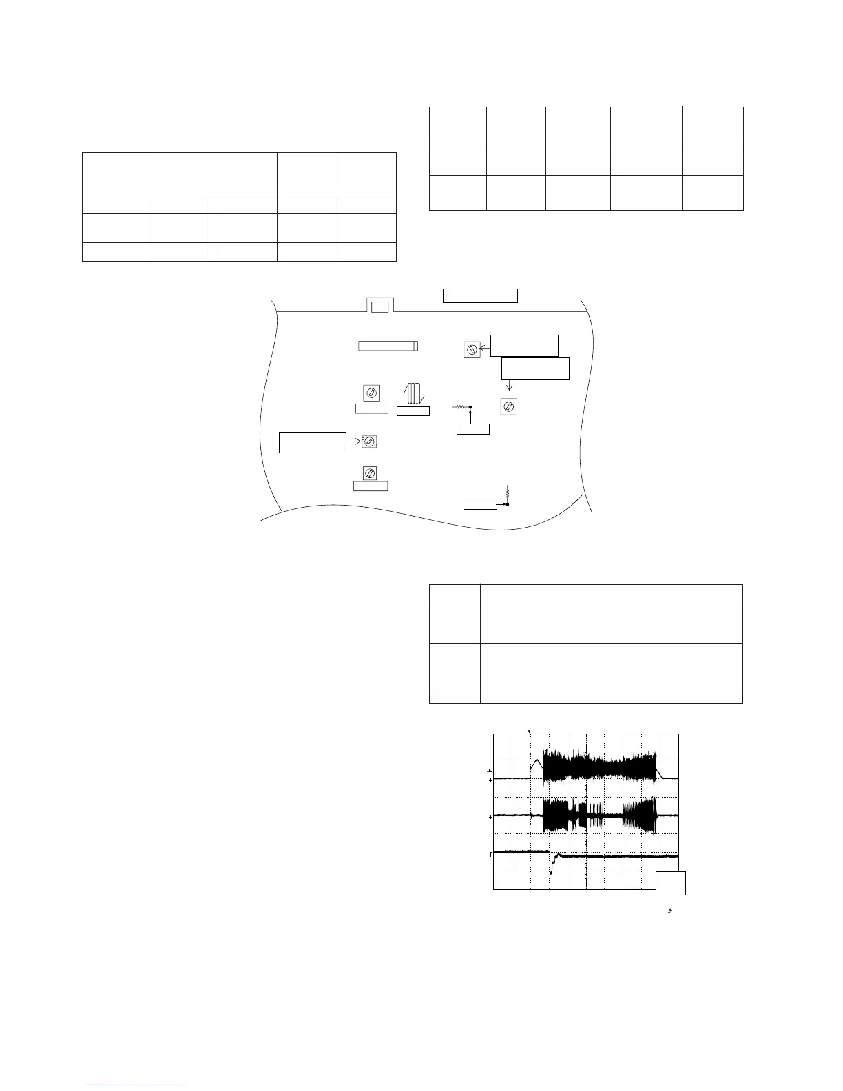
AM IF 450 kHz 1,720 kHz T351 *1
AM Band — 530 kHz (fL): T306 *2
Coverage 1.1 ± 0.1 V
AM Tracking 990 kHz 990 kHz (fL): T303 *1
*1. Input: Antenna Output: TP301
*2. Input: Antenna Output: Speaker terminal
• FM RF
Signal generator: 1 kHz, 75 kHz dev., FM modulated
FM Band — 87.50 MHz T301(fL): *1
Coverage 1.3 V ± 50 mV
FM RF 98.00 MHz 98.00 MHz L312 *2
(10-30 dB)
Test Stage
Instrument
Connection
Frequency Frequency
Display
Setting/
Adjusting
Point
Figure 14-1 ADJUSTMENT POINTS
Figure 14-2
CD ERROR CODE DESCRIPTION
Error
State Code
[Pickup Mechanism Error]
ER-CD00 Pickup mechanism error
ER-CD01 Pu-in SW detection NG
[CD Changer Mechanism Error]
ER-CD10 Changer error
ER-CD11 Initial error
ER-CD20 Tray error
Items adjusted automatically
(1) Offset adjustment (The offset voltage between the head
amplifier output and the VREF reference voltage is
compensated inside the IC.)
* Focus offset adjustment
* Tracking offset adjustment
(2) Tracking balance adjustment (waveform drawing
Fig.14-2 EFBL)
(3) Gain adjustment (The gain is compensated inside the IC
so that the loop gain at the gain crossover frequency will
be 0 dB.)
* Focus gain adjustment
* Tracking gain adjustment
• Adjustment
Since this CD system incorporates the following automatic
adjustment functions, readjustment is not needed when
replacing the pickup. Therefore, different PWBs and pickups
can be combined freely.
Each time a disc is changed, these adjustments are
performed automatically. Therefore, playback of each disc
can be performed under optimum conditions.
IC301
AM IF
FM IF
FM RF
T303
T306
T302
L312
AM
TRACKING fL
AM BAND
COVERAGE fL
T301
T351
FM BAND
COVERAGE fL
MAIN PWB
CNP301
FM/AM LOOP
ANTENNA
TP302
R357
R316
TP301
T
T
EFBL
FDO
TE
Stopped
CH1=500mV
DC 10:1
CH2=200mV
DC 10:1
CH3=1V
DC 10:1
500ms/div
(500ms/div)
NORM:20kS/s
1
2
3
=Record Length=
Smoothing : ON CH1 : 0.000V
CH2 : 0.000V
Main : 100K
Zoom : 2k
Mode : SINGLE
Type : EDGE CH1
Delay : 0.0ns
Hold off : 0.2µs
CH3 : 0.00V
CH4 : 0.00V
BW : FULL
=Trigger==Filter= =Offset=
CH2
v/DIV
200mV
1999/04/05 20:26:47